A horn mouth placed directly on the floor acts as if it's double the size when placed directly on the floor. It's as if there is a "mirror image" of the mouth which double the mouth's effective size. (Or so I've read something like that, I'm just an enthusiastic newb.)
You don't have to put it on the floor but you're giving up a lot of the boundary reinforcement if you lift it up a foot in the air.
You don't have to put it on the floor but you're giving up a lot of the boundary reinforcement if you lift it up a foot in the air.
rjbond3rd said:
You don't have to put it on the floor but you're giving up a lot of the boundary reinforcement if you lift it up a foot in the air.
I understand that at some distance you start to lose a significant amount of boundary reinforcement (it must be a continuum). I don't understand how a foot is too much for the floor but OK for the walls.
dhenryp said:Let me try to ask my question a different way; why is it OK for the mouth to be a foot from two surfaces (the walls) but not OK to be a foot from the third surface (the floor)?
If you put a proper deflector at the back it is not (ie the deflector shapes the corner towards more optimum.
dave
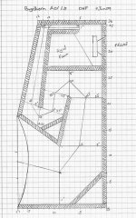
I've completed Rev 1.0 of the bugelhorn plans and it no has a mouth that exits at the floor now. It took a fair amount of massaging to make it fit into the box - the devil was in the detailed dimensions. The final simulated performance is at least as good as the previous design.
I'm attaching the box plan. now and the hornresp simulation in my next post. Please comment ,especially if you have suggestions for improvements, as I hope to start cutting wood this weekend.
I'm attaching the box plan. now and the hornresp simulation in my next post. Please comment ,especially if you have suggestions for improvements, as I hope to start cutting wood this weekend.
Attachments
I've got several more screens from the bugelhorn1.0 hornresp simulation that I'm going to post. I'm not sure if these are good/or reasonable for this time of BLH.
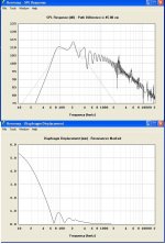
The first is the combined response (at an arbitrary 45cm distance) compared against the mouth response. It seems I can make this picture look as bad as I want by putting in various distances. Am I supposed to use this screen as a guide in calculating how far from the wall(s) to place the driver, or is there another use I'm missing?
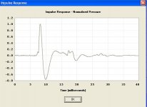
The second screen is the diaphragm displacement. This tells me I exceed max displacement with less than one watt at ~100hz (but the SPL screen posted before says I still get >100db).
Do either of these screens say anything particularly good or bad about the design? They seem pretty ytpical for simulations I've done.
The first is the combined response (at an arbitrary 45cm distance) compared against the mouth response. It seems I can make this picture look as bad as I want by putting in various distances. Am I supposed to use this screen as a guide in calculating how far from the wall(s) to place the driver, or is there another use I'm missing?
The second screen is the diaphragm displacement. This tells me I exceed max displacement with less than one watt at ~100hz (but the SPL screen posted before says I still get >100db).
Do either of these screens say anything particularly good or bad about the design? They seem pretty ytpical for simulations I've done.
Attachments
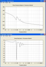
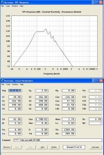
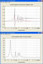
Finally, Acoustical and Electrical impedance.
I don't really understand what acoustical impedance is so I obviously don't know if the picture is good or bad - it is typical of other simms I've done.
I do understand the concept of electrical impedance but I don't know what causes the three small blips but again I've seen them nefore.
I would appreciate any onions or information anyone would like to share on what any of these picture represent and how they look in this case.
Attachments
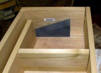
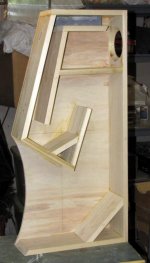
Here is a detail of the throat with one partition removed to show the wedge. The wedge is a simple triangle made of poplar (painted with primer so it shows better in the picture). The first eight inches of the throat is a constant 1.5" width. The wedge makes the expansion correct and gives a throat that is ~1.5" X 2".
The wedge is very easy to cut on a bandsaw or with a jig saw. I used 1.5" poplar because I had it on hand but a piece of 2X4 would work as well.
The wedge is very easy to cut on a bandsaw or with a jig saw. I used 1.5" poplar because I had it on hand but a piece of 2X4 would work as well.
Attachments
dhenryp said:5.5" (14cm) interior width.
We could end up pinching some of the detail in this for Frugel-Horn II (15 cm wide)
Looking forward to seeing how this works out.
dave
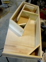
More construction pictures of everything glue together waiting for the top panel. I used 1 X 6 poplar boards for the partitions. Poplar is great to work with; its available at every lumber yard around here, it's always straight and knot free. It's also the right width (by design) so there is no ripping to size required. Finally, since it's solid wood, you can nail and screw into the side edges and get good holding power.
Attachments
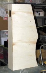
One more picture; of the reverse side. This gives you an idea of what it will look like complete. I haven't decided how I'm going to finish them yet. I'm leaning toward gloss black lacquer side panels, wood for the front and top and painted mouth.
I recently bought the Smith and Larson Speaker Tester measuring equipment so I plan to take and post measurements before too long (hopefully within the week).
I recently bought the Smith and Larson Speaker Tester measuring equipment so I plan to take and post measurements before too long (hopefully within the week).
Attachments
- Status
- This old topic is closed. If you want to reopen this topic, contact a moderator using the "Report Post" button.
- Home
- Loudspeakers
- Full Range
- Bigger Frugel horn (Bugelhorn?)