OK, I did more poking around and can see why some might not like the sound of this amp.
Here is the input chain......
RCA -> LC filter -> 47uf 25v Cerafine -> 100kA pots -> NE5532 -> 4.7uf 50v non-polars -> TA0104A inputs.
I believe the only purpose the NE5532 serves is to invert one channel for bridging. Maybe it acts as a buffer too? I don't see any reason why you couldn't just bypass all that stuff and use your favorite input caps directly into the chip. The "autosense" circuit won't work then, but I don't trust or use it anyway.
We'll see if I have the ***** to try and bypass this stuff.
EDIT: I overlooked the fact you would need to add a gain resistor, so it would be DC blocking cap -> gain resistor, i.e. 34.6k -> TA0104A inputs (pins 5 and 6). Now that I think about it, the opamp there serving as a buffer with gain might not be such a bad idea. I guess it would be a matter of personal preference.
I looked at the data sheet and also noticed that DC offset is dealt with on the inputs as well. What will be the result of not using this and does the amp actually require this and/or already have it?
jeffrae - No I havent tried it on my 901s. BTW, I happen to like the 901series I/II for certain applications. The bad reputation is due to uneducated owners believing they are the best speaker on the planet, which was all know it certainly not the case. But they do have a place(not the trash) and if setup properly, can provide a "good musical experience" especially for non-dedicated music lovers and not critical listeners.
amt
Attachments
I am more of a music Lover then an equipment lover.
I am hoping that these extra watts will help the 901 produce the lower frequencies. The DB boost on the low end via the EQ chews through power..
I use my 901s in my basement wreckroom.. They sould really nice with my progressive rock CD.. (Yes, King Crimson, etc....)
They have been fun. Can't say they are the best, but they do have a pleasant sound. Vocals really stand out. I am guessing the midrange is very strong.
Jeff
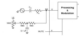
amt, the DC offset adjustment circuit is there on the board. It's not really "in" the signal path, it's in parallel with the input pins, but I'm sure it has the possibility of adding noise. The DC offset without the circuit might be a lot more than we are used to with the small "T-amps" though.
Also, there is no resistor after the cap like in the diagram. I believe the NE5532 is setup for gain, but I haven't checked the resistor values yet to see how much.
Also, there is no resistor after the cap like in the diagram. I believe the NE5532 is setup for gain, but I haven't checked the resistor values yet to see how much.
amt said:I looked at the data sheet and also noticed that DC offset is dealt with on the inputs as well. What will be the result of not using this and does the amp actually require this and/or already have it?
The circuit certainly isn't necessary, but it is nice to be able to null the DC output offsets. This circuit is used on the Ref-T and the Trends amps too.
theAnonymous1 said:It's not really "in" the signal path, it's in parallel with the input pins, but I'm sure it has the possibility of adding noise. The DC offset without the circuit might be a lot more than we are used to with the small "T-amps" though.
Good answers! The only way to find out what kind of DC offset you'd get would be to remove the 1Mohm resistors. I wouldn't expect it to be much different from what we see with the smaller Tripath chips. The main source of noise when using this circuit is the 5V supply that the adjustment pot is connected to. This is most likely the internal 5V regulator. I don't know much about the noise of the regulators internal to the Tripath chips but I bet they could be better. The Ref-T uses this circuit for DC output offset adjustment but uses an external, low noise 5V regulator with filtering. Panomaniac made some noise measurements of the Ref-T and compared them to a stock SI and a Fenice 2020. The Ref-T's output noise was 10dB lower than a stock SI and the Fenice was 10dB lower than the Ref-T if I remember correctly. Clearly there was room for improvement because the Fenice was 10dB lower, but it was 10dB below a stock SI with any added noise from the DC offset adjust and an external 5V regulator (which drew power from the same supply used to power the 14V regulator). Make of that what you will.
BWRX said:Good answers!
I'm trying my best.
I think I've built up the nerve to try an input mod tomorrow. I'm going straight to the input pins with some MKP caps and gain resistor. It's actually really easy to bypass everything else; all you have to do is remove the 4.7uf "non-polars".
As promised, here are some high res pics.
http://i15.tinypic.com/2im4y7n.jpg
http://i19.tinypic.com/4dlu991.jpg
http://i16.tinypic.com/4ic8c29.jpg
http://i13.tinypic.com/3ygl4qf.jpg
http://i19.tinypic.com/2ynigz6.jpg
theAnonymous1 said:
As promised, here are some high res pics.
Looks like Audiosource made a lot of last-minute revisions to that board -- jumpers, scratched-off traces -- pretty funny
 That's the first time I'd seen the bottom of one.
jon_010101 said:Looks like Audiosource made a lot of last-minute revisions to that board -- jumpers, scratched-off traces -- pretty funny
Yeah, that kind of surprised me when I saw it. Some of the wires are for the meters on the front. There is also a set that runs from the volume pots to the input on the board; which is strange because there is already a set on top of the board.
. The cut traces on the right side of the pic go to the middle connection of the series output inductors. The trace was connected to that jumble of resistors on the top.
Maybe all that mess was their last minute effort to get the FCC license needed to sell them. Who knows.
Well I'm either brave or stupid, because I just bypassed the stock inputs. I don't have any resistors of the correct values on hand so I used 50k trim pots. It works, and it sounds good.
I was going to go b***s to the wall and do DC coupling, but there isn't a BIASCAP pin like the other Tripath chips. There is no external access to the 2.5v bias.
One thing I noticed about this chip is that it is internally configured for a very high gain, and then the external input resistor basically just attenuates the signal and sets the input impedance. It doesn't actually change the gain at all. Kind of sucks, because there is quite a bit of noise from the high gain.
Here are some pics of my bypass surgery. The second pic shows the removed non-polars.
http://i12.tinypic.com/4hc3dzp.jpg
http://i15.tinypic.com/2dbkwf9.jpg
I don't know if I'm going to leave it this way or not. I would like to keep it as stock as possible. I might take the Cerafines off the input board, jumper that spot with wire, and then put them where the non-polars were; and changed the opamp to OPA2134.
Oh, and I forgot to mention the rail voltage is +-76.5v.
OK, I've finished doing mods, here is what I settled on:
First, the inputs caps on the input board are needed, the amp won't start up without them. I was hoping they could be removed. I moved the Cerafines to the input of the chip, so I put 56uf 16v Panasonic FC caps on the input board instead. They are the only thing I have more of. I would like film caps all the way around, but I need 12 of them and don't want to spend the money right now.
I removed the NE5532 and put in a DIP socket and an OPA2134.
I also upgraded the opamp power supply regulator caps. The input caps were 470uf 25v standard Rubycon, they are now 1500uf 25 Panasonic FC. The output caps were 100uf 25v CapXon, they are now 100uf 35v Panasonic NHG.
I'm happy with this arrangement for now, although the amp takes a bit longer to turn fully on because it has to charge such large coupling caps on the input. I think the amp sounds good and I'm going to stop before I break something.
http://i13.tinypic.com/2qizt6e.jpg
http://i13.tinypic.com/2usbl9i.jpg
http://i18.tinypic.com/2mnhisg.jpg
No, just one so far. I can't comment on before/after sound too much because I have only done one amp so far and I tested it on my old 3-ways, not the SI's I was bi-amping before the modding.
I think the amp sounds good, minus some hum that was there before the mods and is still there. I don't want to get too carried away messing with stuff because thats usually when it stops working for me.
I think the amp sounds good, minus some hum that was there before the mods and is still there. I don't want to get too carried away messing with stuff because thats usually when it stops working for me.

I've just got mine - looks like God's gift to the diy community! How can you get so much kit for so little? I've got half a dozen T-amps to compare it against and I don't see too much difference.
If it quits working I've got my money back in hardware alone. Thanks amt for starting the thread and thanks to EBay.
A few people seem to be involved so let's hope that the early adopters can get something really refined out of this.
I admire those of us who buy three at a time!
Good luck
Keith
If it quits working I've got my money back in hardware alone. Thanks amt for starting the thread and thanks to EBay.
A few people seem to be involved so let's hope that the early adopters can get something really refined out of this.
I admire those of us who buy three at a time!
Good luck
Keith
digital desire said:Makes me wonder what it is rated at in 4 ohm stereo mode.
According to the TA0104 data sheet, it's 425wpc into 4 ohms, 0.1% THD. Don't know if this amp can do that, given only 20000uF capacitance on the rails and not knowing what the temperature sensors on the heatsink are set at.
If anybody's got some distortion measurement equipment, I'd love to hear what it actually does.
I've got to get some power filtering up and running before I can really enjoy mine. I've got all sorts of 60Hz switching noise on the HT circuit right now, and filtering seems easier than running a new circuit. The high internal gain of the TA0104 is killing me due to picked-up noise.
--Greg
I just got mine.
I noticed some hum on the speakers when my preamp is turned off.. Turning my preamp on even with no source eliminates the the noise. Maybe this is commong with a high gain amplifier when the inputs are left to float.
It's a really nice Match for my Bose 901's.. (Don't Flame Me).. It really helped with Bass and Treble Frequencies.
My AudioSource Amp 3 did a good job, but not great.
FM still works great.. Cable TV working Great... Maybe they fixed the interference with all the trace cutting and jumpering under the access panel on the botton.
I almost want a second one..
Thanks,
Jeff
I just got my amp today. It sounds pretty good with my Magnepan MMGWs. I had been running them with my Marantz receiver. The 7T drove them effortlessly and the Maggies really came alive.
Upgrading the input caps and the caps at the input of the chip sounds like an interesting idea. Has anyone tried replacing the input caps with polyproplenes? Finding 47uF polypropylene caps at a decent price might be tricky, and they're going to be huge caps! I think ClarityCap makes some affordable polypropylenes. Any thoughts?
Upgrading the input caps and the caps at the input of the chip sounds like an interesting idea. Has anyone tried replacing the input caps with polyproplenes? Finding 47uF polypropylene caps at a decent price might be tricky, and they're going to be huge caps! I think ClarityCap makes some affordable polypropylenes. Any thoughts?
- Status
- This old topic is closed. If you want to reopen this topic, contact a moderator using the "Report Post" button.
- Home
- Amplifiers
- Class D
- Big Tripath power fun on ebay