I come from experimentation, for example:
Have you ever measured idle current in a 750VA 50Hz toroid?
This is how it looks like with the small random amount of DC present on my mains line (red trace is current at 1A/1V/div, blue trace is voltage at 100V/div):
And this is how it looks with the 1500W electric heater plugged at half power setting:
Did you know that transformer saturation happens when mains voltage is near 0, and magnetizing current is nearly 0 during the waveform tops? Did you know that the buzz that the transformer makes is a sound similar to the one you obtain when you play the current waveform though a speaker? The current spikes produce sound spikes
And this is how idle current looks with a DC filter. Note the different scales used in each capture. It does not appear clearly to lag 90 degrees to voltage because winding capacitance is partially compensating for it and the hysteresis cycle of the core makes the waveform quite distorted:
Well, after understanding that you may also understand that allowing the primary inductance to frewheel trough a couple of series diodes (allowing it to decide if it is going to have +1.5V or -1.5V across it during a very small amount of time near zero crossing) can already correct for a few milivolts of DC.
p.s: I have not read the Bryston thread.
Have you ever measured idle current in a 750VA 50Hz toroid?
This is how it looks like with the small random amount of DC present on my mains line (red trace is current at 1A/1V/div, blue trace is voltage at 100V/div):
An externally hosted image should be here but it was not working when we last tested it.
And this is how it looks with the 1500W electric heater plugged at half power setting:
An externally hosted image should be here but it was not working when we last tested it.
Did you know that transformer saturation happens when mains voltage is near 0, and magnetizing current is nearly 0 during the waveform tops? Did you know that the buzz that the transformer makes is a sound similar to the one you obtain when you play the current waveform though a speaker? The current spikes produce sound spikes
And this is how idle current looks with a DC filter. Note the different scales used in each capture. It does not appear clearly to lag 90 degrees to voltage because winding capacitance is partially compensating for it and the hysteresis cycle of the core makes the waveform quite distorted:
An externally hosted image should be here but it was not working when we last tested it.
Well, after understanding that you may also understand that allowing the primary inductance to frewheel trough a couple of series diodes (allowing it to decide if it is going to have +1.5V or -1.5V across it during a very small amount of time near zero crossing) can already correct for a few milivolts of DC.
p.s: I have not read the Bryston thread.
Hi Eva,
thanks for trying again.
I am beginning to follow, but all this leading/lagging is getting to me.
I think you are saying that no DC block leads to hum and/or buzzing in the transformer when mains DC is present.
Using only quad diodes can block very small amounts (mV) of mains DC and remove/reduce saturation and consequently hum/buzz.
When significant DC is present on the mains, then only capacitors (with or without protection diodes) can remove the saturation and hum/buzzing.
Am I reading you correctly?
The diodes alone is new to me, thanks once more.
Your displays seem very informative. Can you expand on what they are showing?
Someone mentioned using 3300 uF capacitors for 150 W amp. I find that in simulation that is not nearly enough; more like 18000 uF ones are needed.
Another thing I don't get is how the caps are protected from seeing reverse voltage in the Bryston schematic; normally electrolytics are put back to back to make a single non-polar cap; in the schematic shown, you have them antiparallel to each other; why would the current prefer one cap in one direction and another one in the other? Makes no sense to me.
Another thing I don't get is how the caps are protected from seeing reverse voltage in the Bryston schematic; normally electrolytics are put back to back to make a single non-polar cap; in the schematic shown, you have them antiparallel to each other; why would the current prefer one cap in one direction and another one in the other? Makes no sense to me.
Hi,
some capacitor manufacturers publish acceptable reverse voltage on their electrolytics. This seems to vary from 1000mVpk to 1500mVpk.
If you can ensure that the electrolytics never feel more than a reverse voltage of about this level then they should survive in the long term.
By providing caps in inverse parallel, each cap feels the correct voltage in alternate cycles and hopefully that will allow the oxide film to remain intact.
I suspect that the pair behave better in the long term but at the moment I cannot see/understand the failure mechanism if only caps in one direction were installed (provided that diode protection of about 700mV to 800mV is also installed)
Back to back electrolytics still face the same problem, the reversed electolytic still feels about half the reverse voltage but the correctly polarised capacitor prevents catastophic failure and on the next half cycle the formerly reversed cap gets recharged correctly and again the oxide film gets repaired. I believe it takes a little time for the film to break down and I further suspect that is why both the above senarios work in practice.
Back to your 3m3F and 18mF.
Based on limiting the peak voltage to about one or two diodes Vf then the caps can be sized for NORMAL current into the transformer. For 150W I suspect a value near 10mF to be about right. The bypassing diodes will have to conduct on start up to allow the current to bypass the caps (some still goes through the caps) and similarly if the amp went into some overloaded current limit then again the diodes may have to conduct.
Hi,
yes Bryston and others use the double //diode protection.
This means that the bypass does not operate until at a higher voltage.
That does NOT equate to operating at double the voltage.
The operating voltage still depends on the capacitors value to operating current ratio. It does mean that the bypass works less often and in turn means that the caps will see a more frequent reverse voltage excursion of between 700mV and 1600mVpk but since this range is almost inside the tolerable reverse voltage specified by some manufacturers then Bryston must be happy with their chosen manufacturer's caps for this relatively infrequent duty. It may only occur once a day for 5 to 10mS or upto three 10mS bursts.
You make your choice and see if you can offer a multi year guarantee (is Bryston 10 or 20years?).
I'm missing something here. In simulating this circuit, across the caps there is an approximately sine wave with DC offset equal to whatever the mains offset is. So if there's some long term DC offset, one of the caps is on average exposed to more reverse than normal voltage.
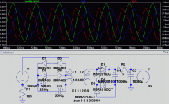
I've attached a screenshot of a simulation of a 20 W supply.
I've attached a screenshot of a simulation of a 20 W supply.
Attachments
I can't tell if your tone in that post is sarcastic, but I'll asume it's not. I find simulators can be useful, while of course being aware that it misses many things and can give wrong results.
V1 is the AC source; I put 100R to ground since in houses here neutral is tied to ground at some point up the power chain. The green trace is the voltage across the capacitors. The AC source I set to have 0.7 V DC offset. The blue and red are currents through the capacitors; one is inverted probably because the simulator assumes direction is determined by the polarity of the electrolytic.
The stuff on the right is bridge rectifier into CRC filter and load, just to simulate a typical audio load on the transformer. The transformer itself is the two coupled inductors; transformer parasitics are not simulated. The graphs displayed are after the circuit reaches operating point, about 2.5 seconds after poweron.
With the current setup, DC offset across the primary is only a few mV as opposed to the 0.7 V of the AC source. Decreasing the capacitors quickly increases the offset, however. This is only a 20 W supply here, which is why these small caps work.


It's not on the plots. It's specified on the V1 source: SINE(0.7 168 60)
The 168 instead of 118 V since LTSpice uses peak amplitude instead of RMS. You can get RMS and average readings for plots by doing Ctrl+click on a plot's label, it will integrate whatever section of the waveform is in the current window.
The LTSpice file is attached. Don't forget that in the display you can enter various expressions, which is how I got the green trace.
The simulation runs faster if you change the coupling K to 1 instead of a fractional value (0.9 in this case), and increase the timestep in the .tran analysis from the current value (I had it low so I could zoom in on peaks to check their exact value; without this number they were not sampled enough and jaggy up close).
Attachments
- Status
- This old topic is closed. If you want to reopen this topic, contact a moderator using the "Report Post" button.
- Home
- Amplifiers
- Power Supplies
- Big Torroidal - Noisy