I have to take back what I said earlier. I looked more closely and the spike isn't that big. it peaks at about 12-18V only.
the waveforms don't show any jittering but when magnified X10, we still get a little jitter. back to square one.
I'm gonna look further into the PCB layout and high current paths.
the waveforms don't show any jittering but when magnified X10, we still get a little jitter. back to square one.
I'm gonna look further into the PCB layout and high current paths.
This turn-off spike is normal circuit behaviour. The only two things that you can do to tame it is to reduce MOSFET turn-off speed or to improve transformer leakage inductance.
The transformer will radiate a large EMI spike at the same time that the spike that you see takes place. Your control circuit will malfunction if it does not exhibit enough inmunity against it.
In my class D car amplifier, this spike was slightly disturbing the channel closer to the PSU when it was very close to clipping and carrier residual fed to the comparator was very small. I did some modifications to solve it (see the thread).
Long wires coming out of the transformer making big loops doesn't help, they actually make the EMI much much worse...
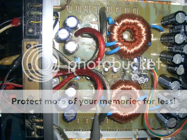
Eva said:The transformer will radiate a large EMI spike at the same time that the spike that you see takes place. Your control circuit will malfunction if it does not exhibit enough inmunity against it.
I think this is indeed what's happening. since the control circuit is mounted very very close to the transformer.
see?
time to do some reading.
 will update this thread soon.
hmmm. I think I know which tracks are causing the problems. 
the culprits are the temp and overvoltage sensing. these use the same op amps inside the TL494 and due to layout constraints, I had a few long tracks around them. I will bypass those and implement them on a separate circuit instead.
hopefully, things get better.
the culprits are the temp and overvoltage sensing. these use the same op amps inside the TL494 and due to layout constraints, I had a few long tracks around them. I will bypass those and implement them on a separate circuit instead.
hopefully, things get better.
I have changed more grounding points, removed all protection circuits so the TL494 is simply an oscillator, changed gate resistors from 22R to 100R to increase turn on/off times
and the EMI lessened but is still there.
I'm thinking there's something inherently wrong with the layout so I'll be changing the board as I have lost hope in saving this one.
and the EMI lessened but is still there.
I'm thinking there's something inherently wrong with the layout so I'll be changing the board as I have lost hope in saving this one.
yup. that's what I did in the previous SMPS but thought I'd make everything in one board to save time. I guess I didn't.
this time though, I'm thinking the controller on one board, protection ckts in another, and all power components on the main board. still thinking if there is an advantage of putting the aux supply regs in a separate daughter boards though.
this time though, I'm thinking the controller on one board, protection ckts in another, and all power components on the main board. still thinking if there is an advantage of putting the aux supply regs in a separate daughter boards though.
before rebuilding this thing, I decided to try the regulated gate drive small scale first.
I will design a powersupply that will drive a 750wrms mono class D amp. (amp section will be another story )
Eva,
provided I do everything right, do you think two pairs of RFP50N06 fets is enough for that amplifier? yes, it is for subwoofer duty and I expect it to run into clipping when pushed hard.
the heatsink I'm planning on using has enough room for eight fets if needed. I was originally thinking of using eight IRFZ44 fets but if you got 800watts out of a pair then I could do the same or more with two pairs?
I will be providing regulated gate drive and do everything right this time. plan everything carefully before going and building stuff. I just got lucky with the amps I did before that up to now are still working fine.
I will design a powersupply that will drive a 750wrms mono class D amp. (amp section will be another story
)Eva,
provided I do everything right, do you think two pairs of RFP50N06 fets is enough for that amplifier? yes, it is for subwoofer duty and I expect it to run into clipping when pushed hard.
the heatsink I'm planning on using has enough room for eight fets if needed. I was originally thinking of using eight IRFZ44 fets but if you got 800watts out of a pair then I could do the same or more with two pairs?
I will be providing regulated gate drive and do everything right this time. plan everything carefully before going and building stuff. I just got lucky with the amps I did before that up to now are still working fine.
IRFZ44N seem to be slightly better than RFP50N06.
I would use them at 70A peak per device or less. For two pairs this translates into 140A peak, or 1700W peak. What rails into what load impedance are you going to use in the end?
You don't need much heatsinking, what is required is very low leakage inductance and good gate drive.
You already know how I would lay it out, I showed a lot of my tricks in the push-pull supply of the 2x150W class-D car amp. Essentially I'm switching the two 2200uF 25V 0.028ohm-ESR low-ESL Panasonic capacitors into the windings though 0.012ohm IRFZ48V. Layout inductance is almost negligible because paths are very short and currents in opposite directions flow through opposite PCB planes. Excess transformer leakage inductance is negligible too, since the magnet wires enter the PCB in the same place where they leave the winding structure. Note that I got a two fold decrease in leakage inductance (and less tall spikes and cooler IRFZ48V) just by rewinding the toroid for better primary-to-primary coupling. 2x120W of music was piece of cake without any heatsink, despite the 60A peaks.
You could consider one toroid and two pairs of MOSFET for each supply rail. Each toroid should use dual secondaries and independent rectifiers. You may lay out the control circuit in a small daughter board and use a PIC for the protection schemes, or even a PIC16F684 with ADC and hardware PWM for everything...
In fact, next time I'm probably going to skip the old SG3525/TL494 stuff. I'm currently using PIC16F690 at 20Mhz in a commercial project and it is powerful enough for controlling a few concurrent processes and doing both high-precision high-frequency hardware PWM for main switching and additional low-precision low-frequency software PWM for non-critical tasks. The ADC is reasonably fast too, it can sample at 25Khz or so. You can even do software-assisted self-oscillating control with the help of the built-in comparators.
that's great news.
I'm thinking of squeezing as much power as I can out of as small as an amp I could make. goal is around 1000wrms into a 1ohm mono load but I was hoping for about atleast 750wrms if I can't meet the 1kw mark. entire amp case/heatsink is about 9" by 10.5"
I have several 25V 2200uF Panasonic FM (or was that FC? the ones with gold lettering and dark blue plastic sleeves) which I'm going to use for primary side filtering.
two toroids is a great idea as I don't have a big enough core that could fit in the case. have an amidon FT 240-77 core but it takes too much board space. I have a couple smaller ones that will fit nicely (about 1.5" dia) and works quite well in a push pull smps. only problem is I don't have available FR rectifiers. I only have one common anode, a common cathode and two doublers on hand and don't know where to get them locally. I also have many to-220 schottky's 90V 10A
so a possible option is one common cathode rectifier for one trafo and one common anode rectifier for another trafo?
or what about independent fets and primaries and paralleled secondaries?
with the power output goal, I'm looking at more than +/-50V rails
since I wasn't able to save the old PCB, I made a new one with a much better layout.
still have the regulated gate supply etc etc as the old board except that this is much smaller. I only used six IRFZ44's per phase and only one trafo.
three aux windings supply gate drive, +/-15 and +5V outputs.
rail voltage is dropped to +/-55V output as not enough copper could fit in the core to minimize I2R losses.
gate drive is regulated to 17V peak and drops out of regulation at 11V input. gate drive is still at 12V peak at 8.2V input.
funny thing though... optimum operating freq is 15kHz only!!!! but drain waveforms are perfect square waves!!! absolutely no heating (except for the gate drive regulator getting warm).
power testing will be done as soon as I get caps that fit the PCB layout. the old 1000uF 100V caps are too big.
did a bit of power testing right up to a couple of watts (without output caps, don't have any that fit) and everything stays cool.
there is no freq jittering issue that I had with the old layout so I guess this will work well.
time to find a heatsink that the SMPS and amp module can fit in.
there is no freq jittering issue that I had with the old layout so I guess this will work well.
time to find a heatsink that the SMPS and amp module can fit in.

- Home
- Amplifiers
- Class D
- Big-t