inertial said:dear mine friend, 8,6x8,6 is not FAT, it is little!
In a bandpass the pipe must be really big, up to 50% of Sd in order to not have "wind"-turbolence from excessive air speed.
This is rilevant at high SPL, of course, so I assume you put in crises the Visatons before.........
friendly,
Paolo

Hi Paolo,
Depends on sound level what air speed will occur. Bigger would mean very long pipes and also more losses.
But explain your self pipes of 50% of the Sd I never see.
Or your mistaken them for a bass reflex and you where looking at a TL.
Theory please foundations of the claim your making Paolo. ( there no such thing as the perfect system it is always a compromise)
Today experimented with placing of the speaker.
40Hz clear audible at normal level 30Hz i bit softer 20 Hz I hear nothing bit I can hear the door vibrate with it
Hey Helmuth , this is not a law court!
And no, i am not mistaking from TL .
BR are one thing ( direct radiator), bandpass are more critique ( indirect radiator).
I have published 20 years ago in my country a program for double-reflex. same problem: the tubes , when correct sized, do not enter in the proper volume!
So, empirycal evidence showed to me that 25% of SD are not sufficent, you need 40% at least, 50% better.
Very simply : one blowing, the other not.
This is the reason to make pipes exponential, to save lenght.
I think there are sure some papers in the AES , who knows?
Cheers,
Paolo
inertial said:Hey Helmuth , this is not a law court!
How says.

I don't believe this.And no, i am not mistaking from TL .
BR are one thing ( direct radiator), bandpass are more critique ( indirect radiator).
I have published 20 years ago in my country a program for double-reflex. same problem: the tubes , when correct sized, do not enter in the proper volume!
So, empirycal evidence showed to me that 25% of SD are not sufficent, you need 40
% at least, 50% better.
Very simply : one blowing, the other not.
This is the reason to make pipes exponential, to save lenght.
O.K show me Paolo and do not claim things you can't explain. Other wise this is a empty discussion.I think there are sure some papers in the AES , who knows?
Cheers,
Paolo
OK Helmuth, you are right, your 10" woofer at 14 mm Xmax peak to peak ,with a little port of about 75 cmq ,do not blow, never.
Ask a new patent, because it is a technical miracle!
You can of course believe what you want, I have made my experiments.
But I do not understand your "stiffness", mine friend.
Paolo
Ask a new patent, because it is a technical miracle!
You can of course believe what you want, I have made my experiments.
But I do not understand your "stiffness", mine friend.
Paolo
inertial said:OK Helmuth, you are right, your 10" woofer at 14 mm Xmax peak to peak ,with a little port of about 75 cmq ,do not blow, never.
Ask a new patent, because it is a technical miracle!
Thanks

The X max is 6mm far as I know.
You can of course believe what you want, I have made my experiments.
But I do not understand your "stiffness", mine friend.
Paolo
I want to learn some thing Paolo.
Every bassreflex has a pipe around 36cm^2. Half the area of mine fat tube.
The pipe radiates al the sound on Fo (the tuning frequency of the port) and the membrane almost stands still. See the cone extrusion on Fo by a simulation.
My simple conclusion every bassreflex has a big problem when your right.
Yes, you are right about BR sizing.
Takes B&W for example. Models 800, 801 Nautilus: they have found that port are source of important measurable and audible distortion
Thus they have developed huge "strange" pipes towards the floor.
Do you think they are exxagerating?
About bandpass, you can take for example Dr. Geddes subs ULF15:
to my eyes they are very generously sized about pipes area.
You can see it at Ai website.
Cheers,
Paolo
About bandpass, you can take for example Dr. Geddes subs ULF15: to my eyes they are very generously sized about pipes area. You can see it at Ai website.
I have calculated it for ya Paolo, area pipe compared to Sd is (208/1133) 1/5 and pipe length 20cm.


The FATBOY has 14cm long pipe and a pipe/piston area difference of (74/337)
 1/4,5 .
 Not a Big difference and de Fat boy is even better because I use also a shorter pipe.

Still no satisfying comment Paolo IMO.

Helmuth said:
Theory please foundations of the claim your making Paolo.
http://www.diysubwoofers.org/misc/portcal.htm
GM
Thanks you GM, very appreciated ! with that formula I have calculated about 189 cmq for the FATBOY ( not sure about Fb , I have inputed 48Hz ) Very good ! Cheers, Paolo
First of all there is no explanation how this formula is determined. So I still don't know how to rate it.
Sd = pi*(Dia/100)^2/4
Vd = Sd*Xmax/1000
Dmin = 100*(20.3*(Vd^2/Fb)^0.25)/Np^.5
Using the formula
Sd=0,0337
Xmax=6
Vd=0,0020022
Fb=48Hz
Dmin= 10,9
A=94,4cmq that is 30% of Sd.
(I do not know how you calculated 180cmq Paolo.)
now I am using 74cmq then I shout increase the area 30%
Can be a option to chance into rectangular 8.6x11cm 19,5cm long.
First I will look at the measurement of the response off the Fatboy.
The first filter design of the fatboy.
I chanced it because it did not please me.
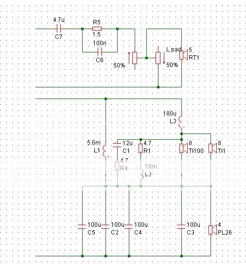
The Ti100 did make to much sub low. Because the 6.8mH coil had to high XL and R.
This made me chance the filter first I had to decrease the XL. To prevent decrease of SPL at minimal Z of the sub around 50Hz.
This made another problem then the Z above 150Hz would be to low below 3 Ohm. With this low impedance off the sub parallel to the TI100 lowmid drivers. I will tell the solution to this later on.
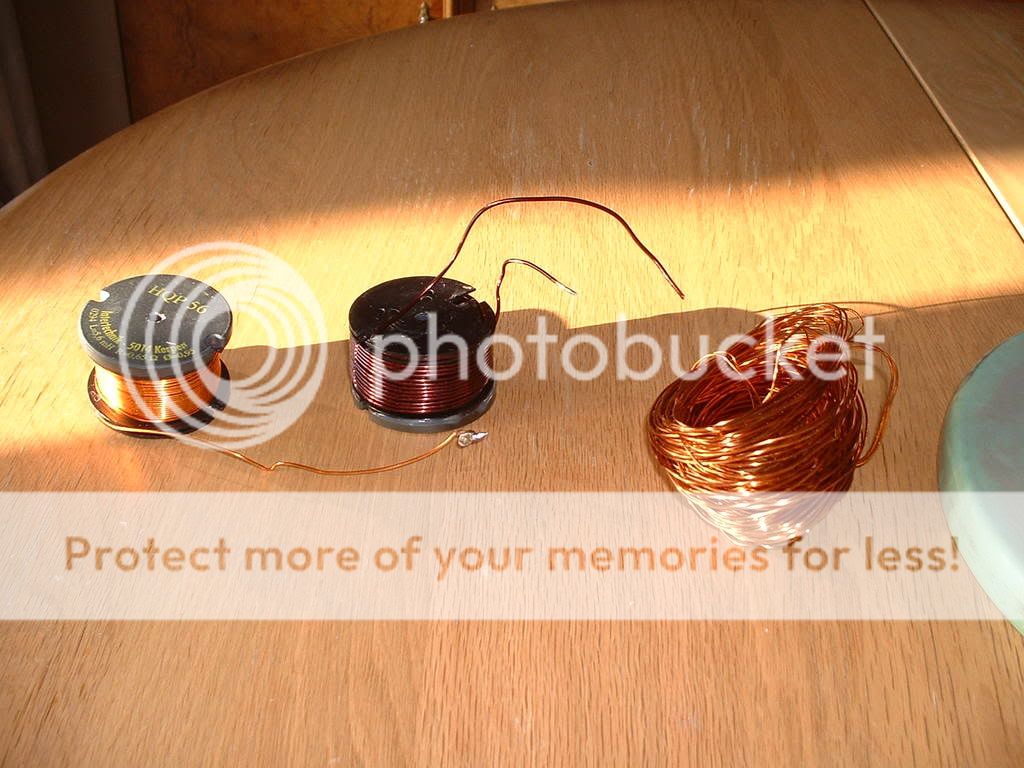
First I chanced the 6,8mH coil.
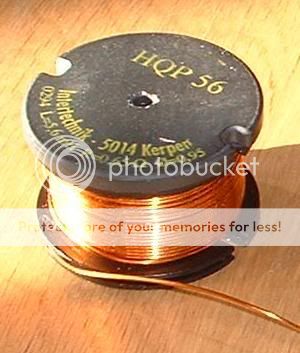
I could buy another coil but I chose to increase the cross area of the wire 3 times and use the same core and bobbin.
the green coil is the new wire 1.6mm diameter. old 0,95mm. the total length is decreased to half. This will lead to a serie resitance below 1,2Ohm. The home made Mega Q coil
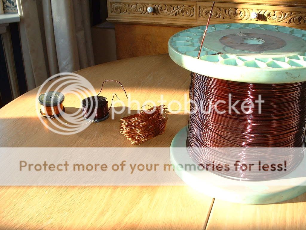
Mega Q. L=1.5mH R<1.2Ohm round 1,6mm When You want to do this your self . The problem is to wind the wire nice close to each other with no air between them to get a good magnetic coupling. Otherwise you will end up with a very low Xl or High R due many windings.
I chanced it because it did not please me.
The Ti100 did make to much sub low. Because the 6.8mH coil had to high XL and R.
This made me chance the filter first I had to decrease the XL. To prevent decrease of SPL at minimal Z of the sub around 50Hz.
This made another problem then the Z above 150Hz would be to low below 3 Ohm. With this low impedance off the sub parallel to the TI100 lowmid drivers. I will tell the solution to this later on.
First I chanced the 6,8mH coil.
I could buy another coil but I chose to increase the cross area of the wire 3 times and use the same core and bobbin.
the green coil is the new wire 1.6mm diameter. old 0,95mm. the total length is decreased to half. This will lead to a serie resitance below 1,2Ohm. The home made Mega Q coil
Mega Q. L=1.5mH R<1.2Ohm round 1,6mm
When You want to do this your self . The problem is to wind the wire nice close to each other with no air between them to get a good magnetic coupling. Otherwise you will end up with a very low Xl or High R due many windings.
@andrewAndrewT said:Vd~0.2Litres=0.0002cubm=0.0337*0.006=Sd(sqm)*Xmax(m)
Minimum Port Diameter
To calculate the minimum diameter of the port required to prevent port noises, you will also need to know the following:
Xmax = maximum linear displacement (mm)
Dia = Effective diameter of driver (cm)
Np = number of ports
Calculate the minimum port diameter from the following equations:
Sd = pi*(Dia/100)^2/4
Vd = Sd*Xmax/1000
Dmin = 100*(20.3*(Vd^2/Fb)^0.25)/Np^.5
where,
Dmin = minimum port diameter (cm)
But,
your posted value of Vd is wrong.
If the effective diaphragm diameter is 207mm the Sd=0.0337sqm.
If Xmax=6mm then Xmax must be entered as 0.006m in the formula.
The units must be consistent to get an answer in cubic metres.
What units are used in the Dmin formula to get the answer in cm rather than m?
Read this.AndrewT said:But,
your posted value of Vd is wrong.
If the effective diaphragm diameter is 207mm the Sd=0.0337sqm.
If Xmax=6mm then Xmax must be entered as 0.006m in the formula.
The units must be consistent to get an answer in cubic metres.
What units are used in the Dmin formula to get the answer in cm rather than m?
http://www.diysubwoofers.org/misc/portcal.htm
IMO they are mixing up cm and mm and correcting it by multiply with 1000 and 100.
And so I did.
Helmuth said:
First of all there is no explanation how this formula is determined. So I still don't know how to rate it.
Sd = pi*(Dia/100)^2/4
Vd = Sd*Xmax/1000
Dmin = 100*(20.3*(Vd^2/Fb)^0.25)/Np^.5
Using the formula
Sd=0,0337
Xmax=6
Vd=0,0020022
Fb=48Hz
Dmin= 10,9
A=94,4cmq that is 30% of Sd.
(I do not know how you calculated 180cmq Paolo.)
now I am using 74cmq then I shout increase the area 30%
Can be a option to chance into rectangular 8.6x11cm 19,5cm long.
First I will look at the measurement of the response off the Fatboy.
Agreed,
made confusion with X-max an X- peak to peak !
Ok , 30% seems good for a BR as I understand the formula.
But you have a bandpass..........this is my point (derived by my
empirical experiments).
Bass reflex and bandpass require different sizing IMO.
In a bass reflex the pipe "cover" a extremly narrow band, no?
In your case you have very narrow band ( quite unusual) but normally others have two octaves ( like the Boston,Kef) . Thus the pipe become more sensible to "chuffing" and you have to increase the section.
Cheers,
Paolo
what is the cut-off level Boston and Kef specify. That is often very misleading.inertial said:
In a bass reflex the pipe "cover" a extremly narrow band, no?
In your case you have very narrow band ( quite unusual) but normally others have two octaves ( like the Boston,Kef) .
Cheers,
Paolo
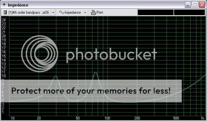
30Hz-80Hz -3dB is 2,33 octave Paolo.
22-110Hz -10dB
It is possible to become wider band result is efficiency decreases.
- Status
- This old topic is closed. If you want to reopen this topic, contact a moderator using the "Report Post" button.
- Home
- Loudspeakers
- Multi-Way
- big bandpass The fatboy