42bit 96kfps Holographic Sound Project
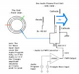
Here is an other design with a rudimentary incorporated Audio to PWM
converter - If someone have a better design they want to share, then by all
means share it d:
The triangle-wave should be somewhere around 40 kHz and very clean.
For lazy and otherwise convenient people, one may hit two flies in one
go by making a lower 20 kHz triangle wave in an audio editor, and then
put that on one side of a stereo audio track and put the audio program
on the next. Then download this to an iPod Shuffle and you have a fully
floating playback unit. The high frequencies will be a little lacking, other
than this, it should be good for testing the rest of the audio spectrum.
The Shuffle above instead of making an optical audio link. The optical link
could be useful for isolating everything from the Plasma Unit: If the high
voltage mosfet breaks down one may under certain circumstances have
a high voltage flash into the low voltage region, the audio modulator etc.
O-I-O
I mentioned earlier something about the grid voltage - I probably meant
to say as follows:
Operating the high voltage field at 40 kV with a light overall drive,
we could have good audio coming from a +500 V (airborne/virtual) grid control
voltage.
If the field was driven higher, the grid 'load' or 'drive' voltage would also have
to be set higher to maintain the same dynamics. So a light drive could be what
we're aiming for here.
The 2SK1317 MOSFET is rated 1500 Volts and 100 Watts, that again gives an
estimated aera of 2.5 square feet, at this stage for parallel/monophonic testing.
Attachments
42bit 96kfps Holographic Sound Project
The ions may be negative, but the place they are coming from is certainly not d:
Yes, it should be possible to modulate, and it would also be very weak (if based on the ion generator).
I think a better place to start is actually over at the Lifter Experiments, to build a real dedicated power supply, etc. Actually, thinking about it, I should build me a Lifter myself")
bigwill said:Do you think it's possible to modulate a 40kV ion wind with a properly biased grid to produce sound? I'm a big newbie so I don't know if it would work...
The ions may be negative, but the place they are coming from is certainly not d:
Yes, it should be possible to modulate, and it would also be very weak (if based on the ion generator).
lne937s said:Just came across this thread- Could you make a prototype out of an Ionic Breeze?
http://www.sharperimage.com/us/en/catalog/productdetails/sku__SI857GRY/catid__101/pcatid__1
That way you already have an ionic wind generater (which also already uses catalists to stop ozone). Then you just need to figure out what needs to be done to make it make sound and what improvements need to be made for audio purposes...
I think a better place to start is actually over at the Lifter Experiments, to build a real dedicated power supply, etc. Actually, thinking about it, I should build me a Lifter myself
56bit 96kfps Holographic Sound Project
The feed from the graphics card is a fat optical link, no worries
Nixie said:Ugh, transformer in the signal path...
The feed from the graphics card is a fat optical link, no worries
coarse PWM
Yes, absolutely. This is just to have something to work with for now.
el`Ol said:I never heard about a good class D amp working with 40 kHz. The digital amps work with 350 kHz, the Tripath has variable switching rate up to 1 Mhz and the highend class D amps from Mircea Naiu up to 11 Mhz.
Yes, absolutely. This is just to have something to work with for now.
42bit 96kfps Holographic Sound Project
That would be the grid area, so the transducer area could be 10 x of that.
Indalhc said:The 2SK1317 MOSFET is rated 1500 Volts and 100 Watts, that again gives an
estimated aera of 2.5 square feet, at this stage for parallel/monophonic testing.
That would be the grid area, so the transducer area could be 10 x of that.
42bit 96kfps Holographic Sound Project
Having another look on your design.
The -40 kV should be positive instead.
The audio signal to the transformer coupled grid would actually
need to be amplitude inverted (not the same as phase inversion!)
first, since the grid has the function of an inverse amplifier when
fed normal/positive signals.
One alternative here could be to modulate the anode voltage,
but then you would not have the grid control...
Lastly, the outermost +10 kV should rather be the air-ground at about
(-) zero Volt (do not touch this point unless is completely grounded to
everything else touchable).
Keep it up though d:
bigwill said:Do you think it's possible to modulate a 40kV ion wind with a properly biased grid to produce sound? I'm a big newbie so I don't know if it would work...
Something like this:
Having another look on your design.
The -40 kV should be positive instead.
The audio signal to the transformer coupled grid would actually
need to be amplitude inverted (not the same as phase inversion!)
first, since the grid has the function of an inverse amplifier when
fed normal/positive signals.
One alternative here could be to modulate the anode voltage,
but then you would not have the grid control...
Lastly, the outermost +10 kV should rather be the air-ground at about
(-) zero Volt (do not touch this point unless is completely grounded to
everything else touchable).
Keep it up though d:
42bit 96kfps Holographic Sound Project
... sometimes I happen to read a datasheet as a certain being is
said to read the bible.... The 2SK1317 is actually rated 10.5 kW.
On touching the Cathode, I encourage people to try this if
it is within a very tiny scaled model (nano Amperes). On a kW scale,
this could also be safe if you actually were standing on the cathode
or grid itself in the first place, even the anode. As long as you were
not trying to reach anywhere outside of that 'potential' / location.
To safely get to and from these electric potentials, a maneuverable Lifter
should be convenient d:
Shuffle
PS. About the Shuffle programming, the audio could be at .75 Volt
while the triangle wave at 1.5 Volts, further tweaking would be possible if
it had a balance control (has it?). The contact pins should be gold plated.
Blah, blah
... and there should in the most recent schematic be installed a ferite core
between the 393 and the 2SK1317 to avoid self-oscillations. I really hope
someone here eventually comes up with a better design
More rambling about high voltage and PWM etc.
What I try to say about high voltages is that these should not
necessarily be treated as a some kind of deadly contiguous
disease.
'Every day' static electricity can be several tens of kilo Volts,
only at very low amperages.
The outer part of a Biefeld-Brown effect based plasma wall
is also the most 'passive' part of the system. It is there to aid
the grid moving the electrons in a outward direction. It could
be made completely safe to touch (especially if the outer
electrode=cathode was made by some fairly high resistive
polymer material).
The prototyping is an other question altogether. This part
can certainly be dangerous. If the system is live, touching
anywhere can be like trying to enter a train moving at full speed;
one needs a special 'vehicle' for that. Super isolated probes is one
safety measure, an other is remote control.
---
I mentioned that the triangle wave feed to the PWM modulator
should fully cover the audio. This is so, however it certainly does
not have to be double the amplitude. This should only be seen
as a measure to be completely certain that the audio never is
converted into DC by overload.
---
About the Amplitude Inverter. I tried to make one, but for now it
only seems to convert everything into square waves. It shouldn't
be all that difficult though: Invert the wave, then bias it so that it
is grounded at zero Volt and that the amplitude then again moves
further downwards the negative region from there. One op-amp
should suffice, only how to do this right...
42bit 96kfps Holographic Sound Project
... not that this would necessarily be such a bad thing
Indalhc said:
a measure to be completely certain that the audio never is
converted into DC by overload.
... not that this would necessarily be such a bad thing
Amplitude Inverter
If the audio program has an amplitude of 2 Volts peak to peak then
the wave zero crossing point from the Amplitude Inverter should be
at - 1 V presicely.
The amplitude inverter is not needed if the grid is fed a PWM output,
however this device could for sure also be interesting to work with.
If the audio program has an amplitude of 2 Volts peak to peak then
the wave zero crossing point from the Amplitude Inverter should be
at - 1 V presicely.
The amplitude inverter is not needed if the grid is fed a PWM output,
however this device could for sure also be interesting to work with.
The Maximus II
Have a look at the Maximus II
http://jlnlabs.imars.com/lifters/maximus2/index.htm
250 grams at 297 Watts, fairly impressive.
- 250 grams modulated would make a lot of sound d:
To Do: Build a Maximus II clone, then add a modulated grid.
(I'm still struggling with the amplitude inverter, knowing
at the same time that this really should be a no-brainer, where is
Tech here
Ozone catalyst - One should not be needed!
And if this still - in spite of everything - turns out to be a problem,
how about using laser
lne937s said:Just came across this thread- Could you make a prototype out of an Ionic Breeze?
http://www.sharperimage.com/us/en/catalog/productdetails/sku__SI857GRY/catid__101/pcatid__1
That way you already have an ionic wind generater (which also already uses catalists to stop ozone). Then you just need to figure out what needs to be done to make it make sound and what improvements need to be made for audio purposes...
Have a look at the Maximus II
http://jlnlabs.imars.com/lifters/maximus2/index.htm
250 grams at 297 Watts, fairly impressive.
- 250 grams modulated would make a lot of sound d:
To Do: Build a Maximus II clone, then add a modulated grid.
(I'm still struggling with the amplitude inverter, knowing
at the same time that this really should be a no-brainer, where is
Tech here
Ozone catalyst - One should not be needed!
And if this still - in spite of everything - turns out to be a problem,
how about using laser
The reason that I mentioned the Ionic Breeze, was for a number of reasons (primarly because it was already built).
However, based upon the fan subwoofers, which vary the pitch of the blades of a fan to create sound (very high SPL at low frequencies)- I had assumed that you would not need that much thrust. Fan subwoofer drivers are basically a variable pitch glorified exhaust fan, rather than a helicopter. Also- using the fan subwoofer as an example- you should be able to just increase and decreasie the voltage (and corresponding airflow), rather than inverting it (the fan subwoofer basically just increases and decreases airflow, rather than reversing it).
Also, although it may not flex too much when a steady current is applied to it, when an audio signal is applied, I anticipate the signal to vibrate the structure more than the air directly (basically an oddly shaped electrostatic speaker). Therefore, I think the structure will need to be fairly stiff and well damped- aluminum foil and thin wires probably won't cut it. The Ionic Breeze probably won't cut it either, but I thought it may be a good place to start.
In terms of Ozone (O3- an ion of oxygen)- I anticipate it will be a problem in this application because it is a problem with much lower powered ion generation applications after an extended period of time- how much I can't say.
Anyway, I am no expert- this is just my best guess, so I hope it helps.
Besides catalysts, ozone can be reduced by changing the overall voltages used with respect to ground (i.e. make the positive electrodes more positive and negative ones less negative or something like that). Check Ionic Breeze related patents for more info, as this is discussed in some of them.
42bit 96kfps Holographic Sound Project
The Ionic Breeze can be good for experimenting with ion flow and such. But I doubt it will go all
the way up to the venerable 'Field' itself. Also it says in the commercial "Uses only 12 watts".
This is certainly more than in the 'pixel sized unit' I have been working with, then again some 5.500
of these are needed to cover one square feet.
About the [inverted] class A operation. I am not attempting to make the air flow change direction.
The grid simply needs a negative amplitude for making positive outwards directed motion.
About the ozone generation, I have strong indications towards that this is just a matter of tuning.
So the problem could possibly be avoided entirely.
The shape of the transducer. Feel free to make your own I expect there to be a multitude
of varieties. On their estimated stability, why not try to modulate a Lifter in flight!
There appears to be quite a number of ways to avoid making ozone. And the Lifter may be inherently 'especially clean'.
lne937s said:The reason that I mentioned the Ionic Breeze, was for a number of reasons (primarly because it was already built).
However, based upon the fan subwoofers, which vary the pitch of the blades of a fan to create sound (very high SPL at low frequencies)- I had assumed that you would not need that much thrust. Fan subwoofer drivers are basically a variable pitch glorified exhaust fan, rather than a helicopter. Also- using the fan subwoofer as an example- you should be able to just increase and decreasie the voltage (and corresponding airflow), rather than inverting it (the fan subwoofer basically just increases and decreases airflow, rather than reversing it).
Also, although it may not flex too much when a steady current is applied to it, when an audio signal is applied, I anticipate the signal to vibrate the structure more than the air directly (basically an oddly shaped electrostatic speaker). Therefore, I think the structure will need to be fairly stiff and well damped- aluminum foil and thin wires probably won't cut it. The Ionic Breeze probably won't cut it either, but I thought it may be a good place to start.
In terms of Ozone (O3- an ion of oxygen)- I anticipate it will be a problem in this application because it is a problem with much lower powered ion generation applications after an extended period of time- how much I can't say.
Anyway, I am no expert- this is just my best guess, so I hope it helps.
The Ionic Breeze can be good for experimenting with ion flow and such. But I doubt it will go all
the way up to the venerable 'Field' itself. Also it says in the commercial "Uses only 12 watts".
This is certainly more than in the 'pixel sized unit' I have been working with, then again some 5.500
of these are needed to cover one square feet.
About the [inverted] class A operation. I am not attempting to make the air flow change direction.
The grid simply needs a negative amplitude for making positive outwards directed motion.
About the ozone generation, I have strong indications towards that this is just a matter of tuning.
So the problem could possibly be avoided entirely.
The shape of the transducer. Feel free to make your own
I expect there to be a multitude of varieties. On their estimated stability, why not try to modulate a Lifter in flight!
Nixie said:Besides catalysts, ozone can be reduced by changing the overall voltages used with respect to ground (i.e. make the positive electrodes more positive and negative ones less negative or something like that). Check Ionic Breeze related patents for more info, as this is discussed in some of them.
There appears to be quite a number of ways to avoid making ozone. And the Lifter may be inherently 'especially clean'.
O3 from UV
UV-radiation is a pretty sure method of making ozone. So avoiding making
UV-rays is a good thing. The lifters operates at comparably higher voltages
(to the ion generating air purifiers) combined with a large distribution area,
so they do not appear to have / emit 'O3-arcs'.
Ozone can be found in nature by the sea and also in the forest, so breathing
this in milder doses could be rather healthy (I'm not rowing d:
42bit 96kfps Holographic Sound Project
I agree on the aluminum foil - and you would probably not see this in an aircraft either.
Electrostatic transducing loudspeakers/ESLs, this is a entirely different method altogether,
for they are; operating within a static field; not operating in 'class A'; have multiple problems
with resonance and resistance (related to internal aerodynamics, diaphragm traction/tension etc).
I guess I don't sound like I'm selling any of these
lne937s said:Also, although it may not flex too much when a steady current is applied to it, when an audio signal is applied, I anticipate the signal to vibrate the structure more than the air directly (basically an oddly shaped electrostatic speaker). Therefore, I think the structure will need to be fairly stiff and well damped- aluminum foil and thin wires probably won't cut it.
I agree on the aluminum foil - and you would probably not see this in an aircraft either.
Electrostatic transducing loudspeakers/ESLs, this is a entirely different method altogether,
for they are; operating within a static field; not operating in 'class A'; have multiple problems
with resonance and resistance (related to internal aerodynamics, diaphragm traction/tension etc).
I guess I don't sound like I'm selling any of these
- Status
- This old topic is closed. If you want to reopen this topic, contact a moderator using the "Report Post" button.
- Home
- Loudspeakers
- Planars & Exotics
- 'Biefeld-Brown effect' based full range drivers