By the way, I had them running at +/- 53 volts.
This is the amplifier I am trying to build:
MBL 8006 clone
This is the amplifier I am trying to build:
MBL 8006 clone
One issue with Darlingtons is the thermal stability. Their gain is almostlinearly increasing with current too - 1 mA might do 100mA or 1A...
ONe possibility is to make sure the bias compensation transistor is on the same metal as the output transistor- not just on the same heatsink but attached (via an insulator) directly on the TO3 can. Don't think Darlington transistors are the best anyway..
John
ONe possibility is to make sure the bias compensation transistor is on the same metal as the output transistor- not just on the same heatsink but attached (via an insulator) directly on the TO3 can. Don't think Darlington transistors are the best anyway..
John
Maybe I'm missing something. Looks to me like the opamp is directly driving the outputs. I don't see how the opamp with +/-15V to 18V rails can swing the power transistors up to the power rails voltages.
Checked it with SPICE. Output can't swing more than opamp rails.
Input Sine at 0.5V and opamp output (V1-RED trace) already clip at +/- 15V. Output of amp is even less (Vout).
Attachments
Circuit is all wrong. Looks like they were attempting a Qsc-usa400 (below 1) but did not get it right. 
Even the QSC is a cheap , economic design method. (Below 2) is the LYNX , it has a real MJE340/350 voltage stage buffering the OP- amp's output ... in my opinion , the better way to do it. OP-amp IPS/VAS "contraptions" are quite prone to instability , very "picky" about IC choice - decoupling (read the lynx amp thread). Discrete is rock solid.
OS
Attachments
Checked it with SPICE. Output can't swing more than opamp rails.
Input Sine at 0.5V and opamp output (V1-RED trace) already clip at +/- 15V. Output of amp is even less (Vout).
Your circuit you have simulated is totally different in the way the outputs are driven...
Look at OS's post above and at the LYNX amplifier. That too doesn't drive the outputs as simple followers hung on the end of an opamp. Its a totally different concept.
Mooly ... Conrad ... if anybody bothered to look at the pictures and documentation will notice that in the common heatsink are located totally 8 transistors and that will be 6 for the output and 2 for the double Vbe
then again the designer claims 120W @ 8 R so 50+50 volt rails looks more like it ...
then again the designer claims 120W @ 8 R so 50+50 volt rails looks more like it ...
Your circuit you have simulated is totally different in the way the outputs are driven...
Look at OS's post above and at the LYNX amplifier. That too doesn't drive the outputs as simple followers hung on the end of an opamp. Its a totally different concept.
How is it different. Look at post #1 schematic carefully. The opamp output is connected to the center of two Vbe multipliers which in turn are connected to T5 and T3. This is replicated in my schematic except for simplicity, the two Vbe are replaced by resistors as are some other components. Don't get distracted by those differences.
The important point to note is with nothing driving the bases of T5 and T3, the signal cannot be amplified beyond the opamp rails. Whereas the QSC and Lynx, the opamp is driving the bases of the VAS transistors. That's why their output can swing to the PSU rails.
Now I see. The OPA445 is a high voltage IC (+-45V).
http://focus.ti.com/lit/ds/symlink/opa445.pdf
R13/16 should not be tied to OP. T1/6 are buffers and if tied together or to earth would give about +-25V to the OPA.
Since it has non-symmetrical PSRR , it is most likely a cascoded- FET single ended IPS , very easily built with discretes.
OS
http://focus.ti.com/lit/ds/symlink/opa445.pdf
R13/16 should not be tied to OP. T1/6 are buffers and if tied together or to earth would give about +-25V to the OPA.
Since it has non-symmetrical PSRR , it is most likely a cascoded- FET single ended IPS , very easily built with discretes.
OS
How is it different. Look at post #1
Hi Michael,
I haven't simulated it lol (the clues in the signature) but there are other aspects too I can't quite reconcile in my head the more I look at it... it just doesn't look right if that makes any sense.
I understand your point... and you may well be correct.
Hi Mooly
Did a few more Spice. This time I added in the voltage regulators T1 and T6. Opamp supply is now at +/- 31.7V instead of +/- 15V. As in the schematic, T1 and T6 bases are tied to the amp's output.
With an input of 1.3V, the opamp output is already into heavy clipping at about +/-38V. Output of amp hard clips at about +/-22V.
What we have is an amplifier running on +/- 48V rails with an output swing of only +/-22V. I don't understand the rationale behind this design but this is what Spice comes out with.
Attachments
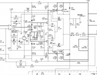
hello Michael thanks for taking the time ...
you may find inetersting to simulate the HILL chameleon schematic which is more or less the same think when it comes to drive ...later models featured a thermistor to automatically adjust the bias
you may find inetersting to simulate the HILL chameleon schematic which is more or less the same think when it comes to drive ...later models featured a thermistor to automatically adjust the bias
Attachments
just for the fun of it ... the above schmatic is a working schematic from a comercial product .... i cloned it in the past and actually works quite welll given the simplicity of the circuit ....
in the original design where drive and output boards was apart cables here and there there was no bias servo and i think that many units failed fron instability ( my opinion messy wiring and no bias servo )
Later models had a thermistor to secure bias stabilty and after that dont know what hapened
even though i had boards made i skiped the design for safety reasons
Hi Mooly
Did a few more Spice.
Thanks Michael... I'm still following this. It is a very strange implementation I agree.
so memory does serve properly ....just found the thread that is realated to this amplifier
enjoy
http://www.diyaudio.com/forums/solid-state/162890-highly-recommended-german-amplifier-schematic.html
enjoy
http://www.diyaudio.com/forums/solid-state/162890-highly-recommended-german-amplifier-schematic.html
Hi sakis
The Chameleon circuit has the same problem. The output cannot swing higher than the opamp rails. I will need the original schematic to sim further.
Below is a fully symmetrical circuit which uses an opamp front end. Instead of two differentials, the opamp drives the bases of two transistors which in turn drive the VAS. This circuit can swing all the way to the supply rails as in conventional designs.
Attachments
- Status
- This old topic is closed. If you want to reopen this topic, contact a moderator using the "Report Post" button.
- Home
- Amplifiers
- Solid State
- Bias Drifting Higher?