The top is at 19v but their source is at 10v (as can be seen as input to drain of bottom FETs), so net result is only about 9v Vds on top FETs.
So do you have first sound yet?
I see what you mean. You are of course correct.
No, no sound yet as I don't like the high DC-offset with the volume all the way down.
I'm trying a different things to see if I can remedy that.
Is this something you have come across?
I may have brainf@rted, with a capacitor on the output, it needs a load...right?
Last edited:
I put the oscilloscope, well the closest thing to it I have atm, a DSO138 on the DAC output and Edcor secondaries.
I got nothing but jibberish. I sent 1Khz sine & square wave via audacity.
Conclusion, the error I made that caused the PS to not reach full voltage killed the CS4397 IC. I've got a new one on the way.
While having the thing apart, I desoldered the 470uF/25V ROA Cerafine output caps and the Silmic II 100uF/25V PS cap. I soldered the Cerafine back in but as PS cap.
I'll put a 1000uF/10V Cerafine as output cap and bypass it with a nice 1uF MKP.
I also ordered some more of the 33R Takman 0.25W metal film resistors to put in parallel with the ones already on the headamp boards. That would put bias from about 8mA to around 10mA per jfet. That, and the bigger output cap with bypass cap should be an improvement with regards to SQ.
I really need at least a Hantek DSO5072P or similar, hard to justify the expense with the missus though as "I have too much crap as it is " lol.
with a capacitor on the output, it needs a load...right?
Yes, something like 270ohms to 470ohms should work to bleed off the cap due to initial turn-on. Otherwise your cans will go thump when you plug them in.
Nice thing with cap coupling is it is inherently safe for your cans.
I got an Owon SSO8192V 100Mhz 1G/s 8" LCD Display 1M Depth Memory VGA Port Oscilloscope for about $270. Works great - 1M depth is very nice and huge screen compared to Hantek.
Last edited:
Well I got a little more done today ")
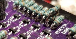
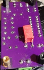
I populated the output capacitors and the extra 33R Takman resistors(on one of the boards as I wanted to test bias in both setups).
I used a 9V battery as power supply.
33R in parallel for 16.5R gave 6.97mA, 33R as is gave 5.30mA.
I did put a Wima MKS2 4u7 across each output capacitor.
I got a 0.001mA difference between all output pairs. I'm ok with that result.
The pics show only one, the first, resistor I put in parallel with the ones already on board.
Attachments
and the purpose is to use it as a preamp before a amp like ACA and would not be using as a standalone headphone amp. I am looking for dual power supply option because the volume control IC (DS1882) needs a +/-7v supply and would like to pair it up wit this before the ACA or any other power amp.can we have this amp modified for dual rail power supplies say +/- 7v or +/-9v instead of around 18v currently being used?
example of DS1882 is given in :
Does anyone know how to use the digital potentiometer DS1882
where its using opamps buffers following.
DS1882 needs very high input impedance stage after it in the range of 1Mohms (buffer or preamp).
Last edited:
Mayday, XRK,
Be careful about adding a small resistor to the output of the cap. The output feeds back into a resistor divider on the input, which sets up the gain of the amp. Adding a small value resistor to the output will change the divider, and effectively reduce the gain to near zero. As designed, the 100K in the divider also functions as a pull-down, bleeding off the output cap's DC leakage. If you need a larger pull-down, scale the divider appropriately, but also be aware that doing so will decrease the input impedance.
On another note, I was intrigued that Mayday was actually building the year-old board, so I dug up my old boards out of the box. But after listening I made a change. I replaced the single 470uF blocking cap with 2 ea 1000uF bipolars (Nichicon UES 1000uF 25V). Its my opinion that the sound is much improved, and actually very, very good. It is generally accepted that when it comes to output caps, bigger is better. Two in parallel doubles the capacitance and halves the ESR. Also, here's a link to an interesting read:
Nichicon Muse ES bipolar caps measured: <-120dB THD, <-140dB IMD
Mayday, XRK,
Be careful about adding a small resistor to the output of the cap. The output feeds back into a resistor divider on the input, which sets up the gain of the amp. Adding a small value resistor to the output will change the divider, and effectively reduce the gain to near zero. As designed, the 100K in the divider also functions as a pull-down, bleeding off the output cap's DC leakage. If you need a larger pull-down, scale the divider appropriately, but also be aware that doing so will decrease the input impedance.
On another note, I was intrigued that Mayday was actually building the year-old board, so I dug up my old boards out of the box. But after listening I made a change. I replaced the single 470uF blocking cap with 2 ea 1000uF bipolars (Nichicon UES 1000uF 25V). Its my opinion that the sound is much improved, and actually very, very good. It is generally accepted that when it comes to output caps, bigger is better. Two in parallel doubles the capacitance and halves the ESR. Also, here's a link to an interesting read:
Nichicon Muse ES bipolar caps measured: <-120dB THD, <-140dB IMD
I typically have 270R load resistor at the output cap to (1) serve as a dummy load when I take measurements, (2) bleeds off the cap. How is single high impedance resistor to ground changing the amp's gain?
So for my pocket amp (now I typically use 2 x1000uF OSCONs for the output coupler with 1uF MKS film bypass). Having RL of 270R doesn't change the gain as verified by LTSpice and by measurment.
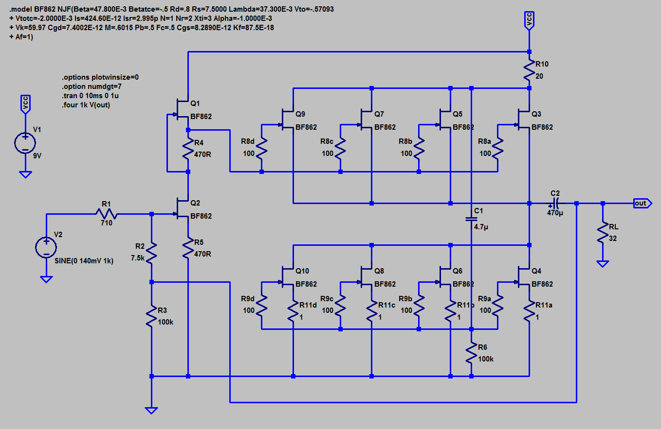
or are you talking about this circuit - which has feedback connected to the output load resistor:
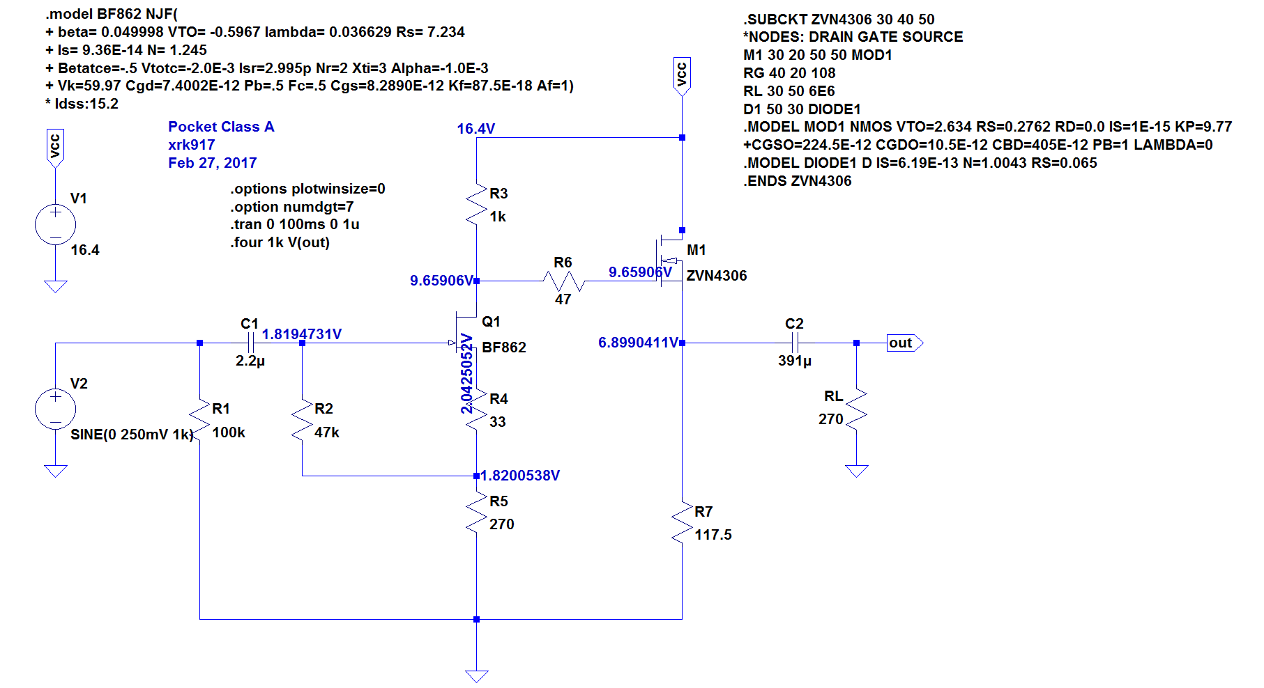
I don't use this amp anymore - much easier to just have a single N-ch MOSFET like ZVN4306GTA than match 8 or 10 BF862's.
Last edited:
...or are you talking about this circuit - which has feedback connected to the output load resistor...
I was thinking of the latter, the one with 10 ea. BF862s, as I think that is what mayday is/was building, and that is what piqued my interest.
But you are correct, adding a resistor to the output does not change the gain. I was thinking that R2-R3 formed a divider which set the gain, when in reality it is R1-R2 which set the gain. Connecting a load resistor, RL, effectively replaces R3 with (R3||RL), which changes only the input impedance. Adding headphones to the mix, RH, again changes the input impedance to (R3||RL||RH). Maybe that's where I got off track? To be honest, I'm not sure what I was thinking at the time.
As Gilda used to say... never mind.
@xrk971,
I have about 95% of what is needed to build the headamp with the BF862 jfet/Toshiba combo that you praised so much. I am planning on 24V smps >> Juma ezpeasy >> cap bank. Does that sound right? I assume you used one cap multiplier for both channels.
Yes, I used one cap mx for both channels. Add a big reservoir cap after cap mx but near each channel PCB to provide some increased left-right crosstalk isolation via the power rail. I typically use a DC-DC step up powered by a 12v 1000mA class 2 wall transformer nowadays. If you really want low noise, put a TPS7A4701 LDO regulator after the cap mx for only 4uv rms noise. You can get these premade into a TO220 package for about $15 on ebay. Request 20v output or get adjustable ones.
For simplicity and great sound, it's tough to beat (within its limited bias current range). If you need more power, more devices are needed and I would say that this amp is quite nice:
Simple High Performance DC Coupled Class A HPA with sub PPM THD
The above amp uses 4 BF862's per channel and a couple of P channel MOSFETs but is all DC coupled and very powerful - probably up to 1.5wrms into 30ohms.
Similar to the Pocket Class A is the larger desktop DCA version with built in cap Mx and CRC - this can crank up to about 145mA bias no problem:
xrk971 Desktop Class A (DCA) Headphone Amp
If you want a middle of the road SE Class A but lower overall THD but same harmonic profile, the Aksa Lender preamp converted to HPA is also great - and it uses the Toshiba 2SA1837:
Aksa Lender HPA
So many choices and so little time.
I appreciate you listing a rundown of different headamps that you've built.
Just a side note - I ordered some BF862s from China and I have a locky_z curver tracer. These weren't working right at all and the curve tracer has an ID feature so I hooked it up and the gate, drain, and source pins were not as expected. When I measured the jfets again with the 3 pins in the correct orientation, they burned out.
I thought that was the end of it but the seller swears he has the right parts and is shipping me more pieces. We'll see. Luckily I have 25 pcs. that I bought a few years ago of the real deal.
- Home
- Amplifiers
- Headphone Systems
- BF862 based SE Class A Headamp without the HEAT