Which of the docs are you referencing, X? Polystyrene and Polypropylene edged out C0G in Capacitor Sounds 3.
C0G apparently came out on top in the newer Groner article linked by mlackey in post #387, though.
And as you said, they are so nice and small!
I didn't know they made big ones...glad you mentioned that. I see up to 1.8uF on Mouser, made by Novacap. Cool...

Maybe I'll be goofy and solder leads onto one and try it in my amp. At 5.5x6.8x2.03mm, I could even stack a few, solder the ends onto leads, and still have room to spare. Sadly, they are like $8 each.
I wonder if anybody has ever reported on the subjective results of C0G in the signal path...
C0G apparently came out on top in the newer Groner article linked by mlackey in post #387, though.
And as you said, they are so nice and small!
I didn't know they made big ones...glad you mentioned that. I see up to 1.8uF on Mouser, made by Novacap. Cool...
Maybe I'll be goofy and solder leads onto one and try it in my amp. At 5.5x6.8x2.03mm, I could even stack a few, solder the ends onto leads, and still have room to spare. Sadly, they are like $8 each.
I wonder if anybody has ever reported on the subjective results of C0G in the signal path...
Last edited:
In Cap Sounds 3, C0G had about 2x the distortion of PS and PP, but still incredibly low , beating the pants off of a WIMA MKS by a factor of 25!
Also, edit to my above post: Mouser wants a minimum order of 1000 for the cap I was looking at. Sheesh. Which 1uF were you looking at, X?
Also, edit to my above post: Mouser wants a minimum order of 1000 for the cap I was looking at. Sheesh. Which 1uF were you looking at, X?
Last edited:
") .
.Considering using 19v SMPS to feed a low dropout TPS7A4700 with sub uV noise and -80dB PSRR - with 18v operating point into amp. Should give 115mA bias current which is plenty for most 50ohm phones. Most meaning not HE-6
+1 on TPS7
I've had good success with the sister part, TPS7A33, which is still available in through-hole package. At similar current, a CRC with 2200uF caps and 4.7R resistor feeds about 30mV AC into the part, and my (out of calibration) meter says about 20uV AC on the output. The TI datasheet has a good example circuit.
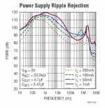
Lt3042 is superior in the audio range psrr has a Peak around 120db for 200mA.
http://www.linear.com/docs/46159
http://www.linear.com/docs/46159
Last edited:
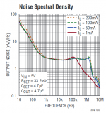
http://cds.linear.com/docs/en/datasheet/3042fa.pdf According to Figures G43/G50 PSRR and noise are getting better with lower current (down to 1 mA).
p.s.: For maximum performance - stability and low noise - you should be careful with C_set both low ESR and low ESL is required.
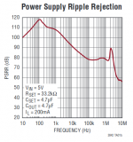
edit: the "cover" graph TA01b of the datasheet is a bit missleading saying that psrr up to 120db can be achieved with 200mA (G43 vs TA01b Cset 0,47uF vs 4,7uF other parameters are the same).
p.s.: For maximum performance - stability and low noise - you should be careful with C_set both low ESR and low ESL is required.
edit: the "cover" graph TA01b of the datasheet is a bit missleading saying that psrr up to 120db can be achieved with 200mA (G43 vs TA01b Cset 0,47uF vs 4,7uF other parameters are the same).
Attachments
Last edited:
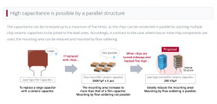
A few posts back I joked about being goofy and stacking SMT caps on top of each other, and soldering on leads. Turns out this is a real thing...recommended by Murata, in fact! They say you can stack up to five of them. This opens up some options...It'd be possible to create a 5x1uF C0G cap to fit in the narrow space for C1 on the PCA. Or even better, a 2x1uF PPS.
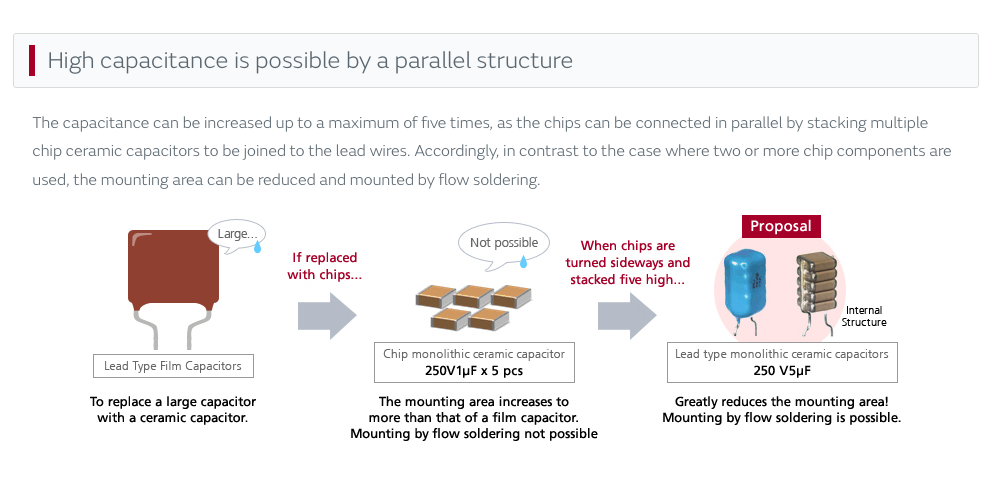
A high capacitance monolithic ceramic capacitor | Leaded Products | Murata Manufacturing Co., Ltd.
A high capacitance monolithic ceramic capacitor | Leaded Products | Murata Manufacturing Co., Ltd.
Attachments
I have these tiny 10uF 50v MLCC caps with leads. I used to use them for input coupling and would bypass with a 1uF film. But now I worry that they may have high distortion since not C0G. Probably X7R so I use them for power filtering only. They look like stacked SMTs. Tiny little packages dipped in epoxy.
With capacitive outputs I did always use 1 nF 100 nF over the real big electrolite output cap, however for input the same, the hybrid of mine has 1 nF and 100pF parallel over 470 nF input cap. better audio pass through, or maybe a hoax, but I did hear the difference, tighter and faster,
PCB ordered: 10µF ELNA SILMIC SMD on input; 4x 220µF OSCON + 0µ22/MKP2 + tbd FKP2 on output; TKD potentiometer; NiMH/NiCd charging electronic.
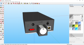
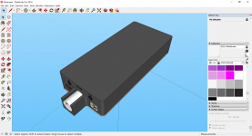
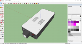
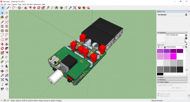
Preparing 3D Printing datas for enclosure online ordering...
JP
Preparing 3D Printing datas for enclosure online ordering...
JP
Attachments
-
 COMPLETE-FRONT.png422.2 KB · Views: 87
 -
 COMPLETE-TOP.png270.8 KB · Views: 83
 -
 COMPLETE-BOT.png278 KB · Views: 92
 -
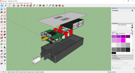 COMPLETE-ISO.png438.3 KB · Views: 106
 -
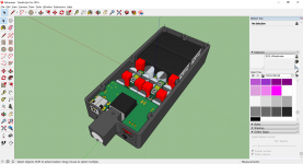 COMPLETE-WITHOUT_COVER.png463.1 KB · Views: 117
 -
 COMPLETE-WITHOUT_CASE.png505.4 KB · Views: 151
 -
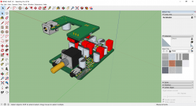 ONLY-PBA_ISO.png719.9 KB · Views: 145
 -
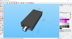 COMPLETE-DIM.png273.4 KB · Views: 96
- Home
- Amplifiers
- Headphone Systems
- BF862 based SE Class A Headamp without the HEAT