The area expansion is Hyperbolic T 0.7 for the A290 the horizontal and vertical combine to ensure the area expansion follows the design rate.If one is trying to match the expansion rate of the horn, what is it? The A290 in its horizontal axis expands at approximately 90° near its throat, transitioning to ~106° at the mouth. One might consider that to be two conical expansions, but is it really? It certainly is not exponential, hyperbolic, tractrix or other typical curved horn profile when seen from the top down.
The horizontal is quite conical which is why the directivity is more constant in that plane than other horns that load with a similar expansion.
Thanks. I will check that against my numbers and report back.The area expansion is Hyperbolic T 0.7
The numbers work out this is an example (not A290) from a Japanese spreadsheet that @docali sent me when I was BEM modelling the A290.Thanks. I will check that against my numbers and report back.
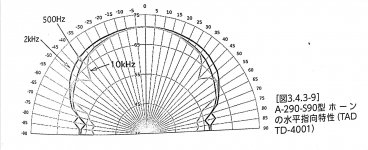
I suspect that the fins help quite a bit.directivity is nearly constant over a pretty wide range.
That’s related to why I am such a big fan of the multi-cell horns.
")
The Yuichi A290 seems to have aspects of a Smith horn and a 5-element multicell horn in the first 200mm, rather than relying on a diffraction throat to control directivity. I'm curious what modern BEM analysis has to say about it.
Also curious if there would be any merit in lining the upper and lower edges of the horn (at the mouth transition) with felt to decrease mouth diffraction.
Also curious if there would be any merit in lining the upper and lower edges of the horn (at the mouth transition) with felt to decrease mouth diffraction.
Last edited:
I don't have a lot of experience with a bunch of different horns , but at 100° the performance seemed surprisingly similar to on axis and at frequencies to beyond 10kHz. I can state that the subjective tonal balance is very consistent over the entire listening room a meter or more forward of the horns - this is not something I have experienced with other horns I have used in this space - most recently the 2380A, but include 2397 smith horns and 2307/2311/2308 conicals with lens, and Eminence H2EA. There were several other exponential horns I no longer remember. Some of these horns went to new homes, others like the H2EA I could not give away.
I guess the question is how much and where to apply the felt. Several have suggested baffles - I'd point out these horns were not designed with baffles in mind, and in my particular case I don't have the space for a sufficiently sized baffle to make a difference. So far the one thing I have determined is that mounting the horn forward of the cabinet and slightly above it can be beneficial.
I have not seen anything in the measurements that would convince me that either baffling or felt are necessary, but that does not mean there would be no benefit either - I simply don't know.
I have not seen anything in the measurements that would convince me that either baffling or felt are necessary, but that does not mean there would be no benefit either - I simply don't know.
Thanks Kevin for the document. I had not seen that before.
I can't get my calculations to fit. @docali How to you measure the mouth width? At the end it's a section of a circle with a radius of 40cm. It's about 106° of the circle, meaning a surface about 74cm wide.
Or should the horn width simply be a straight line from wall to wall perpendicular to the horn axis?
Have a look hereI'm curious what modern BEM analysis has to say about it.
https://www.diyaudio.com/community/...ifications-and-bem-simulation-results.382115/
The fins do have an effect of spreading the high frequencies over 8KHz as Yuichi said in his article. Without the fins the size of the driver limits the upper frequency where there will be faster rolloff moving off axis.
One could build on the continuation of the Hyp/Ex expansion. Then there's the waveguiding version, continuing the curvature of the walls at a local level. Then there's simply 'radially half spacing'.Several have suggested baffles
Examples of elements of each here.
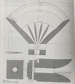
Based on the below diagram where L is length of arc I got 75.5cm (inside dimension, add 2cm for outside dimension) using a measuring tape. Using two rulers, double sided sticky tape and a paper protractor I measured theta ~95°. Take the angular measurement in particular with a grain of salt since there is a lot of stuff in the way

Last edited:
Nice thread, much appreciated. Sort of a halfway house to a multicell horn, with its own set of oddities. What surprised me about my exposure to the Altec A5 was there was less "fingering" than I expected, at least at a 3 to 5 meter listening distance.Have a look here
https://www.diyaudio.com/community/...ifications-and-bem-simulation-results.382115/
The fins do have an effect of spreading the high frequencies over 8KHz as Yuichi said in his article. Without the fins the size of the driver limits the upper frequency where there will be faster rolloff moving off axis.
Thanks Kevin for the document. I had not seen that before.
I can't get my calculations to fit. @docali How to you measure the mouth width? At the end it's a section of a circle with a radius of 40cm. It's about 106° of the circle, meaning a surface about 74cm wide.
Or should the horn width simply be a straight line from wall to wall perpendicular to the horn axis?
As a simplification the construction wave front is like a bended piece of paper (no bending for the vertical). and it is "s" like here:
https://en.wikipedia.org/wiki/Circular_segment
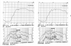
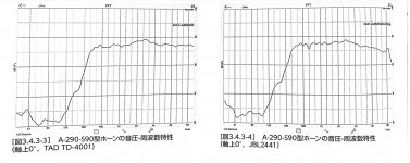
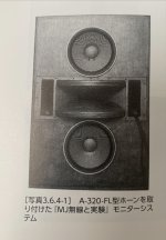
For the sake of curiosity and completeness, there is a derivative of the A290 horn called the A290-S90. Designed by Yuichi himself to make the production process easier and more efficient. It has a 90-degree opening and offers less directivity, making it better suited for use with a supertweeter. Measurements provided with JBL-2441 on and off axis vs TAD-4001 0 degrees. Specifically for baffle mounting Yuichi had a project named the A320-FL.
Attachments
OK. Thanks.
When you did your BEM analysis did you see anything that would indicate a good or bad match of a compression driver?
The driver should provide an almost flat wave front at exit. If the driver contains an adapter like exit section the flare rate should be similar to the horns flare rate. What could be an issue if the driver has a broad exit angle then it would better with short waveguides.
Not to disappoint people to much but the assumption of an acoustic point source is wrong with the consequence that the radial slot at fin end does not provide a spherical wave front radiating into the conical bell (flared). The fins are not phase coherent especially for higher frequencies.
- Home
- Loudspeakers
- Multi-Way
- Beyond the Ariel