You can get autoformers here: Autotransformers | Critesspeakers.com and here: intact audio among other places.
Also curious why Martin used the autoformers before the crossover and not after.
Critespeakers have good prices. $80. They are made to fit Klipsch speakers, but last time I checked Klipsch drivers are not 16 ohm. Does it matter?
No, it doesn't. The autoformer will attenuate the signal and increase the reflected impedance to the source. A shunt resistor can bring the impedance to the desired value for the crossover. You can have a look a Lynn' s initial crossover design for this speaker.
I use Crites autoformers and the are quite good, but plan to get something better.
I use Crites autoformers and the are quite good, but plan to get something better.
Also curious why Martin used the autoformers before the crossover and not after.
I wound the autoformer myself. I didn't want to remake the cross over and saw no benefit in having the autoformer on the speaker. With a 80% Nickel core you can have high impedance (so it is not effecting the LP) and low DCR. But mine probably has quite low power handling. Autoformers used between the cross over and speaker will need modelling, different for every tap. In my set up the cross over just sees the speaker. The autoformer is lumped into the amp output transformer. How that effects the amp is another question..
Hi Gary,
Do you have your design plan published in any way? I mean in terms of crossovers and such. Enough of the pieces has already been written, but I don't recall seeing the whole shebang.
BTW, I grew up in the PNW, mostly in Puyallup. My sister lives in the Portland, OR area and my folks in Chelan, WA, so I am in the PNW a couple times a year.
Josh
The speaker system is unchanged since post #10964, and is configured as follows:
1. RAAL Lazy ribbon, 2nd order high pass at ~8 kHz, 10-ohm tap of tweeter connected to -9.5 dB tap on Slagle autoformer.
2. Radian 745NEO/Be (16 ohm) driver, Azurahorn AH425, 3rd order high pass at ~700 Hz, connected to -17.5 dB tap on Slagle autoformer with 35-ohm swamping resistor.
3. GPA 416-8B Classic Series (alnico), 3 cu ft sealed enclosure, 3rd order low pass at ~700 Hz, Zobel circuit, -3 dB at 61 Hz, attenuation-band notch filter at about 1,500 Hz.
4. AE TD15H-4 plus two AE PR15-700 passive radiators (1 on each side of cabinet), separately powered by plate amp.
Next time you are in the area feel free to stop by for a visit if you have time!
Gary Dahl
Thanks Gary,
Guess I overlooked that post. Also thanks for the invite. I'll reach out next time I plan to be in the PNW.
Josh
It's nice to see this thread going again. Thanks, Gary! Thanks, Martin! Good to see you here, and I'm really pleased that the project has turned out well for both of you.
The sensitivity is set by the woofer, which is 97.5 dB/meter/2.83V rms for the Great Plains Audio 416B-Alnico in the 8-ohm version. The efficiency of the Acoustic Elegance TD-15M is very similar. Both drivers easily accept 50 watts of power, so there's effectively 114 dB of headroom before compression sets in.
The speaker is compatible with DHT-SET amplifiers with power ratings between 3 and 20 watts (using 2A3, 300B, VV32, and 845 tubes), DHT-PP amplifiers with power ratings between 8 and 40 watts (as above), and PP pentode amplifiers in the 20 to 60-watt range (EL84, 6L6, EL34, KT88, KT120, and similar).
Gary Pimm's (Class A) transistor amplifier is radically different than other transistor amplifiers, and works just fine. As for the Nelson Pass designs, I have no recommendation; they didn't work with the Ariels, and I don't know how they'd sound with the new speaker. I do not recommend conventional Class AB-with-feedback transistor amplifiers.
Both 15" drivers are quite flat through 700 Hz, and the AH-425 also has very flat response. (The AH425 was optimized by Bjorn Kolbrek for uniform diaphragm loading over the working bandwidth, and the LeCleac'h profiles have low diffraction and low time storage.)
These are not constant-directivity horns; if that's important to you, there are other profiles. CD horns also require in-band equalization, so the crossover would be more complex.
Hi Gary,
Thank you.
What's the cost of those elements?
What's the sensitivity?
The sensitivity is set by the woofer, which is 97.5 dB/meter/2.83V rms for the Great Plains Audio 416B-Alnico in the 8-ohm version. The efficiency of the Acoustic Elegance TD-15M is very similar. Both drivers easily accept 50 watts of power, so there's effectively 114 dB of headroom before compression sets in.
The speaker is compatible with DHT-SET amplifiers with power ratings between 3 and 20 watts (using 2A3, 300B, VV32, and 845 tubes), DHT-PP amplifiers with power ratings between 8 and 40 watts (as above), and PP pentode amplifiers in the 20 to 60-watt range (EL84, 6L6, EL34, KT88, KT120, and similar).
Gary Pimm's (Class A) transistor amplifier is radically different than other transistor amplifiers, and works just fine. As for the Nelson Pass designs, I have no recommendation; they didn't work with the Ariels, and I don't know how they'd sound with the new speaker. I do not recommend conventional Class AB-with-feedback transistor amplifiers.
Both 15" drivers are quite flat through 700 Hz, and the AH-425 also has very flat response. (The AH425 was optimized by Bjorn Kolbrek for uniform diaphragm loading over the working bandwidth, and the LeCleac'h profiles have low diffraction and low time storage.)
These are not constant-directivity horns; if that's important to you, there are other profiles. CD horns also require in-band equalization, so the crossover would be more complex.
Last edited:
Gary, one quick question with your setup. Actually I have a lot of similar parts in a system I am working on.
What was the rationale for choosing the 16ohm diaphragm for the CD? The 416 is 8ohm and the lazy raal has multiple taps I believe. Does this complicate anything or does the autoformer make this moot with the swamping resistor (I understand the reflected impedance will be very different anyway).
What was the rationale for choosing the 16ohm diaphragm for the CD? The 416 is 8ohm and the lazy raal has multiple taps I believe. Does this complicate anything or does the autoformer make this moot with the swamping resistor (I understand the reflected impedance will be very different anyway).
I am also very interested in learning more about autoformers both as L-pads and crossover slopes. Minidsp 4x10HD make an okay 2nd order filter, but recreating that with passive components feels impossible. Yet my bad attempt sounded more alive than the digital crossover.
Either an 8- or 16-ohm driver works fine in this design. It was originally set up with the 8-ohm 745 (ceramic magnet, aluminum diaphragm). With a 35-ohm swamping resistor, the crossover looks into the parallel combination of the swamping resistor and the entire autoformer coil with the driver connected to one of its taps. Since the impedance of the autoformer is very high, the resulting value is not much below 35 ohms--the driver is fed from a small portion of the coil, and has very little impact on the load seen by the crossover.
When I got the new Radians (745BeNeo), I didn't end up having to change the crossover. The difference in voice coil impedance was insignificant when seen through the autoformer in parallel with the swamping resistor.
The RAAL Lazy Ribbon has five taps, each with its own input impedance and corresponding level of attenuation. I chose the 10-ohm tap and designed the high-pass filter for that impedance. The tweeter level is easily dialed-in by selecting the appropriate tap on the autoformer.
Gary Dahl
Soon I'm going to listen (in my country) to few setups consisting of single horn and single woofer (per side), driven by pair of SET mono-blocks, or 2 SET mono-blocks for the horns + 1 stereo amp for the woofers.
Since the crossover is relatively simple, bi-amping is a good alternative, with the more powerful PP pentode or triode amplifier set aside for the woofer (which needs the power), and a quite small amplifier for the horns (which are extremely efficient, around 112 to 115 dB/meter/watt).
Either an 8- or 16-ohm driver works fine in this design. It was originally set up with the 8-ohm 745 (ceramic magnet, aluminum diaphragm). With a 35-ohm swamping resistor, the crossover looks into the parallel combination of the swamping resistor and the entire autoformer coil with the driver connected to one of its taps. Since the impedance of the autoformer is very high, the resulting value is not much below 35 ohms--the driver is fed from a small portion of the coil, and has very little impact on the load seen by the crossover.
When I got the new Radians (745BeNeo), I didn't end up having to change the crossover. The difference in voice coil impedance was insignificant when seen through the autoformer in parallel with the swamping resistor.
The RAAL Lazy Ribbon has five taps, each with its own input impedance and corresponding level of attenuation. I chose the 10-ohm tap and designed the high-pass filter for that impedance. The tweeter level is easily dialed-in by selecting the appropriate tap on the autoformer.
Gary Dahl
Of course I had to be wrong. The K-55-V is measuring around 11 ohm and the JA6681B measures 12 ohm, so both could be considered 16 ohm drivers.
This makes it much easier and I can almost swap the Klipsch K-55-V for the JA6681B in the many crossover designs that out there that uses autotransformers.
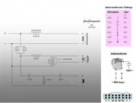
You mentioned a "35-ohm swamping resistor" for your 8 ohm Radian driver. Does this translate to a 10-ohm swamping resistor for 16-ohm drivers like the Klipsch K55-V? In the ALK Jr schematic below there is in a 10-ohm resistor.
Another problem is that I have divided midrange into several horns. But one problem at a time!
These are the ones I have found so far. The schematic is ALK Jr. They look different but can both be used for La Scala, which is similar to my setup and maybe also the Ariel. Apparently with the ALK Jr you can adjust volume as well, but I don't understand where exactly. Maybe the different pins 1-4?
I don't understand the purpose of the knob, except I know it is not for volume. The knob adjust the slope somehow. That is all I know.
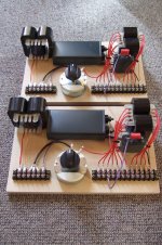
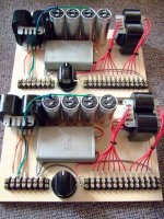
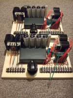
I also read somewhere that big cores sound fuller than smaller cores. Maybe that can explain why some people want to upgrade from using Crites $80 autotransformers. The autotrafos in the picture look expensive enough.
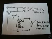
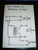
I added pics of the Altec A7 and JBL L300 crossovers, in the two crossovers furthest to the right. And I also added doodles that comes with the expensive German autotransformers. He uses two for every speaker. I wonder why is that.
Attachments
Last edited:
The tradeoffs in autotransformers (and impedance-matching transformers in general) is that bigger cores carry more current at low frequencies, but interwinding capacitance increases as the windings grow in size.
Since there's no requirement to carry current down to 20 Hz (unlike an conventional output transformer), the core can be much smaller, and the windings optimized for HF performance. The highpass crossover in front of the autotransformer efficiently isolates it (and the compression driver) from deep bass.
To recap, the autotransformer and "swamping resistor" work together. The transformer multiplies the impedance of the compression driver by the square of the turns ratio, which is the same as the voltage-division ratio. Put another way, if the voltage division is 5:1, then the impedance multiplication is 25:1. The entire impedance curve of the compression driver (and horn) is multiplied by this ratio.
The swamping resistor is in parallel with the input of the transformer. What was a very high and variable impedance curve is now almost entirely dominated by the parallel resistor. This means the load for the highpass filter is now close to resistive, instead of the complex reactance of the compression driver + horn combination.
Similarly, from the perspective of the compression driver, the source impedance drops to a very low value, and the varying impedance of the highpass filter largely disappears. It doesn't have the near-infinite isolation of bi-amping, but isolation between the passive filter and the driver is improved.
Since time-domain artifacts (like diffraction and internal horn reflections) appear in the impedance curve, these are not fully correctable by conjugate-matching the crossover (which is the more usual practice). I prefer isolation when the impedance curve of the driver is reflecting complex (and slightly nonlinear) time-domain behavior from the electroacoustic system.
The lowpass filter is directly connected to the woofer, so it does require impedance correction (Zobel for VC inductance), but is also fortunately a low-Q Bessel/Gaussian filter that is fairly insensitive to impedance variation.
Last edited:
No wait. Your Radians are probably 16 ohm. I got it wrong again.
In the ALK Jr, he seems to adjust volume with the 1-4 pins. So the autotrafo in this case is just like a 1st order slope, I guess. Then together with the 1st order 20+20uF (=40uf) caps he should have 2nd order. Right?
Edit: Lynn, I read your comment after posting. So the 20+20uF caps protect the autotrafo from bass. Interesting.
Last edited:
Lynn, Thanks for the clear explanation of the autoformer function. I guess in my case where I have a very small autoformer ahead of the cross over it is going to be easily saturated by the bass. It is not audibly distorted only because of the low levels - or maybe it is. I guess it would need to be something like the output transformer if it was to be rated for full power. Well I hate to rebuild the cross over but good to know what is going on.
martin
martin
Lynn, I read your comment after posting. So the 20+20uF caps protect the autotrafo from bass. Interesting.
Yup. Even something as simple as a single cap protects the autotransformer from bass. A lot.
Core saturation from LF energy, in my experience, is a high-order function. A single octave make a huge difference in power-handling. Think about it: if you're asking a valve amplifier to handle 20 Hz at full rated power and low distortion, the output transformers are seriously large, and very expensive. Relax the requirement to 40 Hz, the transformers get a lot smaller, and surprise, the HF gets better, too, thanks to less interwinding capacitance.
Cost goes down, too, since bigger cores require more complex winding schemes, with more labor. (The cost driver in a transformer is the labor to wind all of those layers and connect them together; fewer layers, simpler interleaving, and the cost goes down.)
Extend that to 500 Hz. No bass at all, from a transformer design perspective, and not only that, the power levels going into the compression driver are very small, from tens to hundreds of milliwatts (never as much as a watt in domestic applications). Thus, nickel cores are entirely practical, which improves low-level linearity (nickel cores are the preferred choice for microphone transformers). The autoformer is going to be about the size of a studio-quality 600-ohm line-driver transformer, not an output transformer.
No requirement for shielding, either. Just keep it a few inches away from the other air-cored inductors in the crossover.
Last edited:
- Home
- Loudspeakers
- Multi-Way
- Beyond the Ariel