Might be worth confirming if the 4 degrees quoted by Radian is not the wall angle (ie one side). 4 degrees seems too small for the subtended angle.
To avoid confusion, the wall angle of the 425 horn throat is of course 4 degrees. (8 degrees subtended angle). I measured the 6681 wall angle and it is 4 degrees.
martin
To avoid confusion, the wall angle of the 425 horn throat is of course 4 degrees. (8 degrees subtended angle). I measured the 6681 wall angle and it is 4 degrees.
martin
Good point. Considering the absence of reflections in the 0.5 mSec range, the Radian is probably the same 8 degrees as the Altec/GPA driver. There's certainly no visual mismatch when you look down the horn. I just need to drill the four holes for the Radian for my personal AH425's - the classic three-hole pattern for the Altec doesn't match, of course.
As got prior comments about bass quality, well it all depends on how it measures and sounds here in Colorado. Whichever cabinets I end up with, they're far too big to haul up from the downstairs basement, so they'll get assembled in my garage, which is fortunately pretty clean and reasonably free of auto emissions.
There are several alternatives to the vented-box alignment. One is going down the Gary Pimm path of a 2-cubic-foot open-back U-box (filled with Bonded Logic UltraTouch) for the 416. When I visited Gary a month ago, he showed me the EQ and crossover for his setup (all done with software plug-ins on a quiet PC), and the Beta 8's he's using have almost no EQ at all. The filled U-box does not have any baffle peak (I saw the measurements), and extends nicely down to 100 Hz, where it meets the dipole subwoofers.
If the Beta 8's don't need EQ, a bigger driver like the 15" should be even better - in fact, I suggested to Gary that he try a 15-incher for himself. As it happens, he has both Altec and Electro-Voice 15-inchers in his basement ... so I suggested he try it sooner rather than later, he might be very pleased with what he hears. His U-boxes are plenty big enough for a 15-inch driver, and EQ, if necessary, is trivially easy to adjust on the PC.
The upside/downside to the Gary Pimm path is a requirement for a pair of subs that sit directly under each U-box. Then again, the bass from Gary's dipole subs is the best I've ever heard - stupendously deep and lightning-quick stop-starts on percussion. He's using a pair of 15-inch prosound drivers in each W-cabinet dipole, with 800 watts of prosound amplification and plenty of EQ. The dipole subs are flat as a pancake from 20 Hz to 100 Hz, with room modes nicely EQ'ed out. Being dipoles, of course, there aren't as many modes to remove, making it easier for the EQ adjustments.
The impact of the subs is unbelievable. It feels like a car has crashed into the house; everything in the room moves - the wood floor, the coffee-table, and of course the listener. Anyone that thinks dipole bass is wussy has never heard anything like Gary's setup. And it's not all brute force, there's a sense of pitch to the deep bass that isn't there with most commercial subwoofers.
Last edited:
Hi Lynn,Instead of being an unwanted and uncontrollable loss term, it becomes part of the LF alignment. There's also a desirable side effect of the system becoming less sensitive to dynamic variations of Qts. Using a very wide or tall vent, with felt lining, introduces resistive loss, as well as damping organ-pipe modes. Rather than "aperiodic", it is simply an enclosure that is transitional between vented and closed-box, with the vent primarily resistive rather than inductive. What I like is the woofer is no longer so critically dependent on amplifier damping, a good thing if the speaker is going to be powered with zero-feedback triode amplifiers.
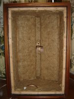
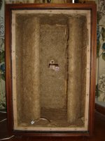
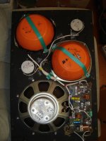
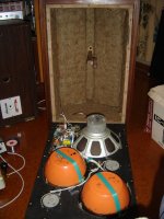
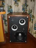
Interesting comments on resistive-vent systems. Do you think the design in the images below counts as resistive vent ?
You can't tell from the angle of the pictures but the rear corners of the cabinets have large chamfers, on each of those chamfers there is a slot/vent which is 15 inches high (roughly half the total height of the cabinet and centred half way up) but only 1 inch wide which enters the cabinet just behind the turnable baffles, and as well as the enclosure walls, both sides of the turnable baffles are lined with the same lining. (The actual slot itself in the cabinet wall which is approx 1" deep doesn't have lining though)
These were built by my Dad in 1971 (and updated to the driver configuration shown in the pictures in 1977) and I always really liked the sound of them, despite the odd driver layout they are incredibly dynamic and whilst probably not as accurate as many modern speakers manage to have an almost eery sense of you-are-there realism and presence.
When I was first starting to get interested in speaker design around 2000 or so one thing that always baffled me about these speakers was that although they are bass reflex (or so I thought) they do not have the classic double hump impedance curve at all.
There is a clear minimum of visible cone excursion which varies in frequency depending on where the adjustable baffles are set - about 36Hz with them right back parallel to the chamfered rear corners, rising to about 48Hz with them set parallel to the front panel, which actually divides the cabinet into two separate volumes with only a 1" gap between the two baffles. (Total box volume is approximately 90 litres)
So clearly there is bass reflex loading occurring, however the only impedance peak is the lower of the two peaks you would normally expect - with the baffles towards the back it peaks to about 20 ohms at 20Hz, however there is no peak in the 40-60Hz region, just a very very tiny broad bump only increasing from about 8 ohms nominal to 9 ohms or so from memory somewhere around 45Hz, but barely noticeable on the graph.
Its easy to assume that there is just so much loss in the vents that the system is close to a closed box but its anything but. There is a LOT of output from the vents, and over a very wide frequency range. Blocking them off reduces the bass output by many dB over a wide frequency range well up into the midbass. (There is still a lot of output from the ports as high as 65-70Hz even though the box is "tuned" to 36Hz)
Cone excursion is also amazingly small at rather high output levels. Yes they do start to move quite a bit below 30-35Hz, but anywhere from about 35Hz up the cone excursion is barely visible even at quite high SPL. (Floor loading from the woofer being close to the floor probably helps a bit here)
The bass doesn't have amazing extension, its good down to about 30Hz including room gain and that's all, but its very tight, dynamic and clean with no boom or overhang. Kick drums sound amazing on them for example.
So what are they exactly ? Just a bass reflex with a lossy vent ? Could they be some sort of coupled cavity when the baffles are parallel with only a narrow gap coupling the two cavities ? They don't seem to lend themselves well to traditional lumped component analysis...(I can't get any match between measured results for SPL and impedance using a normal T/S simulator, even if I play with the vent loss figure)
(pictures taken in 2005 when a bit of revamping and redesign of the networks was done)
Attachments
Last edited:
By measurement and audition, both the Altec/GPA 288 and the Radian 745Neo are excellent choices for the AH425, with very flat responses (+/- 1 dB) in the 700 Hz to 7 kHz range. No equalization was required - the system response is as flat as any soft-dome tweeter, but with 10~20 dB more headroom.
Martin of Azurahorn is using the rare Yamaha driver, and he's getting really good results as well.
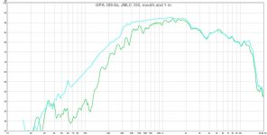
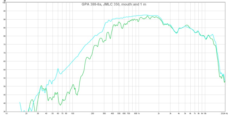
Hi Lynn and others, I'm following this tread since the beginning and find it VERY interesting since the design is going in the same direction that my system. I use 2 tapped horn subs and one closed box sub followed by JBL 2235 in closed boxes (65 to 900 Hz) , then JMLC 350 horns with GPA 388-8A (900-6000 Hz) and JMLC 1000 with Celestion CDX1-1425. My system is multi amplified and digitally crossed.
The 388 GPA is a ferrite version of the 288 with aluminum membrane , not Pascalite. As quoted, you say that your medium combo measures nearly flat. This is not my case and I'm wondering why. Look at the joined measurements (SPL is relative). A broad hump in the medium with a nasty drop at 3700 Hz. Does anybody sees any explanation? Of course those drivers ca be equalized but at the expense of reduced output and I have difficulties to adjust the crossover on both sides of the used spectrum , 900 and 6000Hz.
Christophe
Attachments
In the past, I have tried various resistive designs just to understand the potential.
Basically, you want to tune resistance so that the impedance only flattens out the Fo of the driver without creating too much load on the driver itself. Port response will tell you things too. But generally it is best to avoid port output from having a concentrated frequency output. It is best to have the energy of the port spread out.
An externally hosted image should be here but it was not working when we last tested it.
An externally hosted image should be here but it was not working when we last tested it.
Basically, you want to tune resistance so that the impedance only flattens out the Fo of the driver without creating too much load on the driver itself. Port response will tell you things too. But generally it is best to avoid port output from having a concentrated frequency output. It is best to have the energy of the port spread out.
Hi Lynn,
Interesting comments on resistive-vent systems. Do you think the design in the images below counts as resistive vent ?
You can't tell from the angle of the pictures but the rear corners of the cabinets have large chamfers, on each of those chamfers there is a slot/vent which is 15 inches high (roughly half the total height of the cabinet and centred half way up) but only 1 inch wide which enters the cabinet just behind the turnable baffles, and as well as the enclosure walls, both sides of the turnable baffles are lined with the same lining. (The actual slot itself in the cabinet wall which is approx 1" deep doesn't have lining though)
These were built by my Dad in 1971 (and updated to the driver configuration shown in the pictures in 1977) and I always really liked the sound of them, despite the odd driver layout they are incredibly dynamic and whilst probably not as accurate as many modern speakers manage to have an almost eery sense of you-are-there realism and presence.
When I was first starting to get interested in speaker design around 2000 or so one thing that always baffled me about these speakers was that although they are bass reflex (or so I thought) they do not have the classic double hump impedance curve at all.
There is a clear minimum of visible cone excursion which varies in frequency depending on where the adjustable baffles are set - about 36Hz with them right back parallel to the chamfered rear corners, rising to about 48Hz with them set parallel to the front panel, which actually divides the cabinet into two separate volumes with only a 1" gap between the two baffles. (Total box volume is approximately 90 litres)
So clearly there is bass reflex loading occurring, however the only impedance peak is the lower of the two peaks you would normally expect - with the baffles towards the back it peaks to about 20 ohms at 20Hz, however there is no peak in the 40-60Hz region, just a very very tiny broad bump only increasing from about 8 ohms nominal to 9 ohms or so from memory somewhere around 45Hz, but barely noticeable on the graph.
Its easy to assume that there is just so much loss in the vents that the system is close to a closed box but its anything but. There is a LOT of output from the vents, and over a very wide frequency range. Blocking them off reduces the bass output by many dB over a wide frequency range well up into the midbass. (There is still a lot of output from the ports as high as 65-70Hz even though the box is "tuned" to 36Hz)
Cone excursion is also amazingly small at rather high output levels. Yes they do start to move quite a bit below 30-35Hz, but anywhere from about 35Hz up the cone excursion is barely visible even at quite high SPL. (Floor loading from the woofer being close to the floor probably helps a bit here)
The bass doesn't have amazing extension, its good down to about 30Hz including room gain and that's all, but its very tight, dynamic and clean with no boom or overhang. Kick drums sound amazing on them for example.
So what are they exactly ? Just a bass reflex with a lossy vent ? Could they be some sort of coupled cavity when the baffles are parallel with only a narrow gap coupling the two cavities ? They don't seem to lend themselves well to traditional lumped component analysis...(I can't get any match between measured results for SPL and impedance using a normal T/S simulator, even if I play with the vent loss figure)
Loudspeakers with resistive elements in the vent, open-back enclosures filled with Bonded Logic UltraTouch, or filled transmission lines don't seem to model very well with lumped component analysis. I suspect the lumped component analysis fails to describe what these enclosures are really doing, just as Webster horn theory fails to describe real-world horns.
We shouldn't be shocked at this outcome. Before Butterworth filter theory arrived in the late Fifties, crossovers had to be designed with the hopeless M-derived methods, which just didn't work. That's why early crossovers were so simple; the filter theory just wasn't there. It was the advent of color television, with its severe requirement for flat group delay, that forced the development of better-defined filters.
The first horn theory I've seen that matches theory and reality was Bjorn Kolbrek's BEM methods, which has the unsettling implications that the late-Seventies constant-directivity horns (Altec's Manta-Ray and JBL's Bi-Radial) were developed with theories that just don't work.
My attraction to loudspeakers that have intentional resistive terms in the electroacoustic transfer characteristic is based on my reluctance to make the power amplifier the most critically tuned element in a high-order filter. I just don't trust amplifiers that much, having designed three of them from scratch. Surprisingly small changes in amplifier topology can mimic design changes in the loudspeaker, which tells us that more is going on in the amplifier than accounted for in simple models.
I don't put any emphasis on the impedance curve of the bass driver + enclosure; that doesn't really tell me much about the acoustic filter characteristic I'm interested in. It would be like trying to design a crossover by looking at its input impedance, which would be a frustrating exercise.
What is great importance is a spectral direct measure of what's coming out the vent, or the rear of a filled U-box. If it's a narrow spectral peak, well, we have a classical Theile/Small vented system. If it's broader (like an octave or more), it's something different, something that doesn't fit in the lumped component analysis. This is where looking at the group delay of the vent output might be interesting, and how it sums with the driver output at typical room locations.
I've heard pretty much the same things as you in subjective terms for resistive-vent enclosures; not only that, but our friend Planet10 uses nearly the same words for his favorite resistive-vent boxes. In principle, closed-box and vented-box enclosures should sound pretty similar well above the F3 frequency, but I hear very different sound: with the same drivers, the closed-box often sounds shut-in and dynamically compressed, while the vented-box has noticeable "overhang" and dynamic slurring on fast drum passages (Indian and Mideastern drumming most noticeably).
This is where resistive-vent, filled U-boxes, and TL's seem to pull ahead. It's subjective, but they sound "faster" and have less overhang than other types of enclosure, without falling into the trap of the occasionally thin sound of dipoles.
I've noticed the same things in amplifier design. Power supplies sound "faster" when I intentionally insert resistive loss terms into parts of the circuit that would otherwise be purely reactive (LC), or portions that would be undefined (current sources). My guess is the circuit recovers faster from overshoot conditions when there is real, resistive-loss term to absorb the stray energy.
Similarly, bass drivers are not as perfect as we like to think. There are complex nonlinear behaviors in the magnetic system, suspension, and spider, and relying solely on the amplifier to damp these is probably not a good idea - partly because the amplifier is also nonlinear, and in Class AB amplifiers, most nonlinear at low levels.
Hi Lynn and others, I'm following this tread since the beginning and find it VERY interesting since the design is going in the same direction that my system. I use 2 tapped horn subs and one closed box sub followed by JBL 2235 in closed boxes (65 to 900 Hz) , then JMLC 350 horns with GPA 388-8A (900-6000 Hz) and JMLC 1000 with Celestion CDX1-1425. My system is multi amplified and digitally crossed.
The 388 GPA is a ferrite version of the 288 with aluminum membrane , not Pascalite. As quoted, you say that your medium combo measures nearly flat. This is not my case and I'm wondering why. Look at the joined measurements (SPL is relative). A broad hump in the medium with a nasty drop at 3700 Hz. Does anybody sees any explanation? Of course those drivers ca be equalized but at the expense of reduced output and I have difficulties to adjust the crossover on both sides of the used spectrum , 900 and 6000Hz.
Christophe
If the measurements are to be trusted, it's only flat from 400 Hz to 2 kHz; the range above that looks unusable. I'd be very reluctant to apply boost equalization where the response has multiple notches and falls like a rock.
Two thoughts: is the air-seal between the horn and compression driver good? Does the exit of the compression driver exactly match the entrance to the throat, or are there rough spots and a lot of hand-sanding? I've seen $15,000 audiophile speakers where the entrance to the wood horn was crudely done with a pen-knife, complete with wood splinters that partly blocked the horn entrance.
Next, maybe the Altec is just plain defective. There were some years when Altec's quality control was pretty bad. You can usefully cross-check this by getting a pair of Radian 745 (I recommend the Neo) drivers - they're not that expensive from prosound vendors.
Last edited:
It's subjective, but they sound "faster" and have less overhang than other types of enclosure, without falling into the trap of the occasionally thin sound of dipoles.
I would certainly agree. I have the Lowther PM6A 16 ohm silver voice coil (whew) and Eminence Delta 8 drivers mounted nude on a simple minimal baffle on top of a pair of Dave's TL towers.
The TL matches the two nude drivers perfectly and meshes with the dipole without any audible grit. The Lowther and emminence are to gen 2 EnABL and neither exhibit any shriek, shout or time "beat" between the three elements, whizzer and two cones. The crossover is a simple first order series, set for 200 Hz between Lowther and Delta 8, without allowing for the series added L&C factors in the crossover components and the Delta 8 runs to 20Hz. Doesn't respond to 20 Hz of course.
The TL's are driven by inexpensive SS plate amps and are currently running up to a 200 Hz cutoff and their phase control is adjusted to about -50 degrees from 0. The sound is effortless, transparent, for the first time out in front of the drivers, along with side to side and deeply in back. All of this without any thinness being evident. Interestingly all of the sound stage parameters can be altered by minute adjustments to phase, cutoff and amplitude for the TL's. I do mean minute, it would be nice to have a bit better resolution to the pots, so I may see to that shortly.
The amp is an AudioPrism Debut with 2,4,6 & 8 ohm out taps, so it isn't yet working at it's best. New Level three outputs and a considerably beefed up power transformer, for Christmas, should help.
Bud
Attachments


Last edited:
Hi Bud,
You've been busy! It seems that it's doing what you had wanted/ anticipated/ planned on since the beginning. Will you be having a private showing in the future? I'm sure a certain 200% Gentleman, along with a few others of a slightly courser nature, would love to hear these wonders of the Sonic Art.
The drawings look great and I can imagine that they sound absolutely splendid!
Best Regards,
Terry
There are many considerations in how to read impedance plots. Basically they are only an indicator of how well the driver is controlled, and have no decisive relationship with the frequency response. Ted Jordan had actually explored a different modeling method which looked much better to me. Too bad nobody further derived appropriate math to relate it with physical design....
I don't put any emphasis on the impedance curve of the bass driver + enclosure; that doesn't really tell me much about the acoustic filter characteristic I'm interested in. It would be like trying to design a crossover by looking at its input impedance, which would be a frustrating exercise.
What is great importance is a spectral direct measure of what's coming out the vent, or the rear of a filled U-box. If it's a narrow spectral peak, well, we have a classical Theile/Small vented system. If it's broader (like an octave or more), it's something different, something that doesn't fit in the lumped component analysis. This is where looking at the group delay of the vent output might be interesting, and how it sums with the driver output at typical room locations.
I've heard pretty much the same things as you in subjective terms for resistive-vent enclosures; not only that, but our friend Planet10 uses nearly the same words for his favorite resistive-vent boxes. In principle, closed-box and vented-box enclosures should sound pretty similar well above the F3 frequency, but I hear very different sound: with the same drivers, the closed-box often sounds shut-in and dynamically compressed, while the vented-box has noticeable "overhang" and dynamic slurring on fast drum passages (Indian and Mideastern drumming most noticeably).
This is where resistive-vent, filled U-boxes, and TL's seem to pull ahead. It's subjective, but they sound "faster" and have less overhang than other types of enclosure, without falling into the trap of the occasionally thin sound of dipoles.
I've noticed the same things in amplifier design. Power supplies sound "faster" when I intentionally insert resistive loss terms into parts of the circuit that would otherwise be purely reactive (LC), or portions that would be undefined (current sources). My guess is the circuit recovers faster from overshoot conditions when there is real, resistive-loss term to absorb the stray energy.
Similarly, bass drivers are not as perfect as we like to think. There are complex nonlinear behaviors in the magnetic system, suspension, and spider, and relying solely on the amplifier to damp these is probably not a good idea - partly because the amplifier is also nonlinear, and in Class AB amplifiers, most nonlinear at low levels.
Amplifier and it's interaction with the power supply is very critical. Additionally if ground is considered as single point, the dynamics of the return current and it's interaction with the power supply and the PSSR is largely ignored. The amplifier really should not be used to damp the speaker though it's feedback loop, I think lots of people have explored this and the results are positive. In fact, when the speaker itself imposes a near constant resistive load to the amplifier, it produces less interaction with the amplifier.
Phase response of the total system turned out to be more important than I had thought. If I do a design where the phase response of total system is more linear, the result is "good" vs "good with flying flying scores" as described by one reviewer under a little test where I just asked him to see if I am on the right track or not in terms of fidelity.
krzys said:<snip> A broad hump in the medium with a nasty drop at 3700 Hz. Does anybody sees any explanation? <snip>
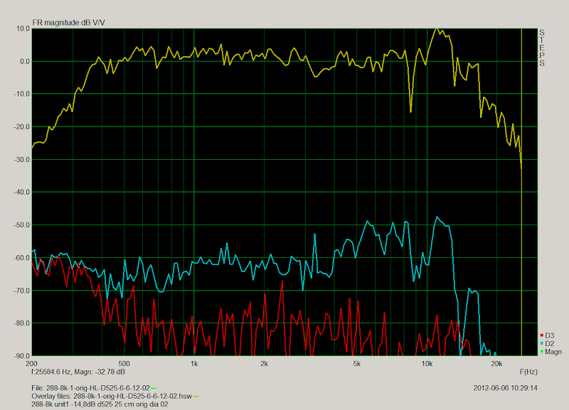
- The explanation could be as simple as a poorly fitted diaphragm ( on your GPA 388 ) .
- Here's the distortion ( & FR ) plot of a poorly fitted ( new GPA ) diaphragm ( belonging to Pano ) put into one of his 291/288 driver bodies .
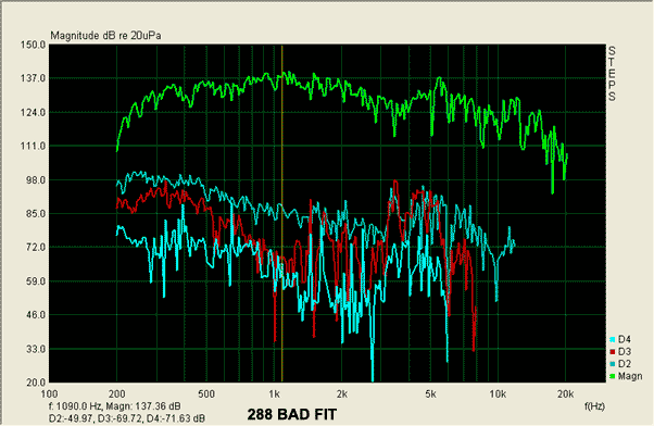
More ( from Pano ) ;
Notice the simularity to your ;
- I recommend you remeasure the distortion content ( using STEPS, HolmImpluse or REW ) & then look in the 3.7Khz area.
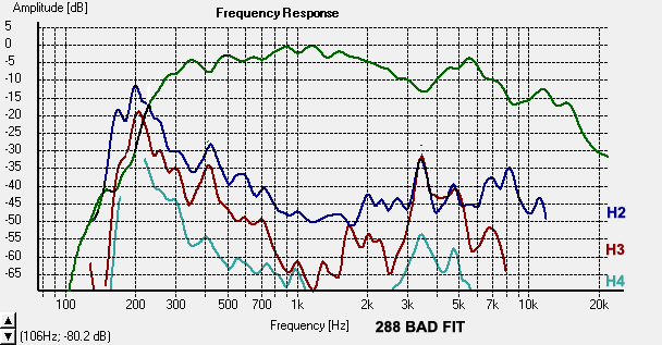
- If H3 has climbed as high as H2 in the region , then your diaphragm is poorly fitted .
- If that's the case, simply refit/realign it .
H2 vs H3 should look something like this ( when the diaphragms are fitted properly ) ;
or this

Lynn Olson said:<snip> Next, maybe the Altec is just plain defective. There were some years when Altec's quality control was pretty bad. You can usefully cross-check this by getting a pair of Radian 745 (I recommend the Neo) drivers - they're not that expensive from prosound vendors. <snip>
- He doesn't have an old Altec driver, it's a newer ( "pan-cake body" ) 388 made by GPA .
<> EarlK
Pano,
- My plot (5th pic ) has a pretty small dip at 8K ( coinciding with a similar reduction in H2, fwiw ) / leading me to believe it is a mechanical phase cancellation ( of some sort ) .
- The (4th) pic with the 8300 hz suckout belongs to Coen , of Why-Do-My-288-8Ks-Sound-Like-Cr@p ? fame, ( sorry I wasn't a bit more clear on that ) .
<> EarlK
Thanks Earl. I'll have to look back at my 288 measurements on a different horn, but I think the dip is always there. You see a little on the Emilar horn, but not nearly what I get. The wavelength is just about the same as the distance from the diaphragm to the exit of the driver throat.
If it's like with the small format drivers, it, and the peaks/dips above it are all due to the discontinuity created by the driver/horn junction causing reflections back to the driver's internal horn throat. I smoothed out/extended the HF response of a pair of 802D/511 combos by replacing the cardboard spacer with a metal one sealed with wax paper gaskets, then align honed the assembly.
The downside of course is that this would have to be redone each time a different horn was used if you wanted to maintain this level of HF performance.
GM
The downside of course is that this would have to be redone each time a different horn was used if you wanted to maintain this level of HF performance.
GM
Lynn ... can I get some recommendations for resistive slot ports on my new boxes. I see two choices for area, a % of the cone area or use a standard speaker program (Win ISD or UniBox) to get close. Length is the problem with slots as they are harder to adjust than typical round ports. There is also the Onken phenomena with the ports hugging a wall. I noticed the port area on my Jensen Ultraflexs is just about equal to the 12" Sd in the original design and are very short. I'm not sure if Cyr-Marc's Onken spreadsheet would be of much help.
Thanks, Zene
Thanks, Zene
Hi Lynn, Earl K, Pano and others, thank you for your responses and help. Indeed, I bought two GPA 388 in April 2010. Both measure the same so I thought that it is normal with the aluminum membrane (part number 23763) but I got frustrated when I read that 288 measures flat on Azura horns. I have chosen GPA driver because I read some negative impressions about the SQ of Radian drivers.
My horns are Autotech JMLC 350 made from fibreglass with very smooth throat, 8 deg entrance angle, steel mounting flange and 388 have neoprene soft gasket. I think that I can conclude that neither the horn nor the gaskets are the problem.
Searching in the tread I found that we had the same discussion in December 2009, page 646 posts from 7th, post 6452.
I then must conclude that GPA drivers are not reliable and could not be recommended (or that the response isn’t flat at all). I cannot accept that a driver paid 340$ need some work and realignment. I will open them and try to align the membranes and will report the result.
At GPA site I found this:
http://www.greatplainsaudio.com/LgDrvrDiaRepl.pdf
The instruction recommends using a spider shim but I don’t have this shim!!!!!
Insert the spider shim that was shipped
with the new diaphragm/voice coil into
the voice coil gap, as shown in Figure 5.
Figure 5. Spider Shim Installed Into Voice
Coil Gap
10. Carefully place the new diaphragm/voice
coil assembly onto the dowel locating
pins. DO NOT install the diaphragm hold down
screws at this time. The shim sets
the voice coil into the precise position
necessary for proper sound reproduction,
while the free locating pins move to
accommodate the slight adjustment
needed to properly align the entire
assembly.
Christophe
Why not contact Bill and have this discussion with him. Perhaps he would offer other solutions, although you have not posted response to compare to. I have some 288K coming, so I guess we will see about them.
The FR response of my drivers is attached in post 8304 and EarlK posted a fair number of responses in his post. The problematic FR seems to be recurrent to Altec/GPA drivers and I would expect that the problem has been addressed by the manufacturer
Chris
Chistophe, as far as I know, the spider shims come only with new diaphragms so that you can align them when you install them. My 288s were 291s, I added the new diaphragms to them. Alas, mine did not have the locating dowels, so alignment was very tedious, even with the spider shims.
Your 388 drivers should have come aligned.
Your 388 drivers should have come aligned.
- Home
- Loudspeakers
- Multi-Way
- Beyond the Ariel