Did I see an oblique reference to this previously on this thread?
http://aa.peavey.com/downloads/pdf/qwp1.pdf
I think someone said it isn't good enough for our purposes so I haven't mentioned it before. It sure would be easier to make for Diy'ers, but of course that isn't the main goal here. The author acknowleges the problem of diffraction at the mouth in most horns. Possibly instead of the foam (or felt ) at the edge of the mouth, there could be a 4" radius fold back at the edge. That is quite easy to do with molding when you have a square section!
It looks pretty reasonable to me, and a simple and effective edge termination. It even reminds of some of JohninCR's posts using expanding foam to create a smooth termination for the waveguide.
Going through all (OK, many) of the OB posts in the many different forums over the last several years has been interesting reading. Our friend Thorsten has had a lot of good things to say, and I appreciated this Open Baffle Study as well.
Going through all (OK, many) of the OB posts in the many different forums over the last several years has been interesting reading. Our friend Thorsten has had a lot of good things to say, and I appreciated this Open Baffle Study as well.
Hi MBK,
Point accepted in relation to transients.
I still think however, that electrical compensation for baffle induced peaks will make music reproduction sound less natural because the pre and post transduction compensations will work in different time frames; ie. not coherent.
Only the steady sine response measured in time isolation will become flattened.
Thus the 'Q' of edge induced peaks should be minimized by mounting the driver at one edge of a baffle, with it some way down from the top in relation to the frequency range required.
Cheers ........ Graham.
More Links
I'd like to quote Rudolf from another discussion:
"Ferekidis has shown that a baffle, which does not exceed 2.2 times the effective driver diameter, works best with regard to minimised edge diffraction. The complete derivation is only available in German:"
http://www.randteam.de/papers_lf/daga_2001-lf.pdf
Rudolf Finke's Dipole-Analysis site is at:
http://www.dipolplus.de/
Wish I could read German! This is interesting stuff. The graphs alone are quite informative.
subjective compromises
Hi
Sadly there simply is NO ideal speaker position on an OB. And to my belief, no such thing like an IDEAL OB shape as well..
Try yourself with EDGE and also vary the listening angle horizontally and vertically and also the size of the speaker in relation to the baffle size – you will see immediately.
(Lynn, could you please post the "rudder shape" you found to have good response – anything I tried in this direction had really inferior FR. Didn't quite understand your description I'm afraid.)
What CAN be done is :
1.) to optimise for a relative low impact of different listening angels at an estimated listening distance.
2.) to optimise for easy equalisation – not necessarily maximal flat FR
This was my aim for the test baffle above with the given speaker.
Also here we HAVE to live with a compromise. As you see in the CSD the FR is quite different from what is the decay which simply means you have to balance to something that is an SUBJECTIVE optimum in listening perception.
Listening to the test baffle, it indeed sounds slightly more "natural" when the compensation of the notch at 544 Hz is reduced from the 6 dB shown in the measurements to about 4 dB. For XO I use a simple 6 dB at aroud 2 kHz .
The Dynaudio speakers also have to break in some longer, as they didn't play for more than a decade now.
Greetings
Michael
Hi
Thus the 'Q' of edge induced peaks should be minimised by mounting the driver at one edge of a baffle, with it some way down from the top in relation to the frequency range required.
Sadly there simply is NO ideal speaker position on an OB. And to my belief, no such thing like an IDEAL OB shape as well..
Try yourself with EDGE and also vary the listening angle horizontally and vertically and also the size of the speaker in relation to the baffle size – you will see immediately.
(Lynn, could you please post the "rudder shape" you found to have good response – anything I tried in this direction had really inferior FR. Didn't quite understand your description I'm afraid.)
What CAN be done is :
1.) to optimise for a relative low impact of different listening angels at an estimated listening distance.
2.) to optimise for easy equalisation – not necessarily maximal flat FR
This was my aim for the test baffle above with the given speaker.
I still think however, that electrical compensation for baffle induced peaks will make music reproduction sound less natural because the pre and post transduction compensations will work in different time frames; ie. not coherent.
Also here we HAVE to live with a compromise. As you see in the CSD the FR is quite different from what is the decay which simply means you have to balance to something that is an SUBJECTIVE optimum in listening perception.
Listening to the test baffle, it indeed sounds slightly more "natural" when the compensation of the notch at 544 Hz is reduced from the 6 dB shown in the measurements to about 4 dB. For XO I use a simple 6 dB at aroud 2 kHz .
The Dynaudio speakers also have to break in some longer, as they didn't play for more than a decade now.
Greetings
Michael
Hi

Greetings
Michael
Ferekidis has shown that a baffle, which does not exceed 2.2 times the effective driver diameter, works best with regard to minimised edge diffraction
Greetings
Michael
Re: subjective compromises
Sorry about the slow posting of the Edge simulations. This partly due to my awkward personal situation: I have a Mac TiBook downstairs, where I am typing now, as well as a Mac G5 and an AMD X2 PC upstairs, where I do the simulation work. It's easier to keep the leg elevated with the laptop - well, perched on my lap - than it is sitting down at the desk, where I have to take frequent rests and raise my leg on the desk. If I get too involved, I tend to forget to attend to my physical needs (raising the leg and massaging it).
I'm still at the stage where the leg is prone to edema, and I try to avoid keeping it down for too long. The lack of progress on the X-rays from February 20th to March 20th was due to edema, as far as I can tell, and the progress since then is the result of good blood flow in the leg, which is why I try to avoid sitting in positions where it is lowered and not being active.
It's occurred to me that it might be a while until I can fly again, and maybe not ever in the cheap seats in tourist class - that would be risking Deep Vein Thrombosis, which is a risk for air travelers in trapped in too-small seats for long international flights. I'm 6 foot 2 inches, not a small guy, so sitting in tiny seats for a long time is especially uncomfortable - and now, dangerous.
Putting that physical grossness aside and pending the PC -> Mac file transfer, here's a verbal description: imagine the rudder of a Swissair 747 - although kind of smaller, maybe 1.2 meters high. The top of the rudder is 600 mm across, and the bottom is 850 mm. The top overhangs the bottom by 150 to 200 mm.
Visualize the front of the aircraft facing to the right. Now forget the airplane, just think of its rudder, with the leading edge on the right, and the trailing edge and overhanging portion to the lower left. Remember I am also simulating the floor reflection, so there is a virtual rudder underneath the real one - it now looks like the swept wings of an aircraft, pointing towards the right.
The widerange driver is on the upper right, close to the top surface and right (leading) edge of the baffle. The midbass and bass drivers are mounted more or less in a vertical line below the widerange driver, although I run the Edge simulation looking at the WR driver by itself (1 driver) and also with all 6 drivers running at once. When I look at the single WR driver by itself, I'm not interested in the floor reflection, but am interested in all of the baffle diffraction, including the mirror-image baffle beneath the floor.
Since there's a reasonable chance I'm going to tip the baffle backwards by a few degrees, in order to time-align the bass and WR drivers, I move the virtual microphone between 1 meter high and the middle of the baffle height, as well as looking at 3, 12, and 100 meter distances.
mige0 said:
Lynn, could you please post the "rudder shape" you found to have good response – anything I tried in this direction had really inferior FR. Didn't quite understand your description I'm afraid.
Greetings
Michael
Sorry about the slow posting of the Edge simulations. This partly due to my awkward personal situation: I have a Mac TiBook downstairs, where I am typing now, as well as a Mac G5 and an AMD X2 PC upstairs, where I do the simulation work. It's easier to keep the leg elevated with the laptop - well, perched on my lap - than it is sitting down at the desk, where I have to take frequent rests and raise my leg on the desk. If I get too involved, I tend to forget to attend to my physical needs (raising the leg and massaging it).
I'm still at the stage where the leg is prone to edema, and I try to avoid keeping it down for too long. The lack of progress on the X-rays from February 20th to March 20th was due to edema, as far as I can tell, and the progress since then is the result of good blood flow in the leg, which is why I try to avoid sitting in positions where it is lowered and not being active.
It's occurred to me that it might be a while until I can fly again, and maybe not ever in the cheap seats in tourist class - that would be risking Deep Vein Thrombosis, which is a risk for air travelers in trapped in too-small seats for long international flights. I'm 6 foot 2 inches, not a small guy, so sitting in tiny seats for a long time is especially uncomfortable - and now, dangerous.
Putting that physical grossness aside and pending the PC -> Mac file transfer, here's a verbal description: imagine the rudder of a Swissair 747 - although kind of smaller, maybe 1.2 meters high. The top of the rudder is 600 mm across, and the bottom is 850 mm. The top overhangs the bottom by 150 to 200 mm.
Visualize the front of the aircraft facing to the right. Now forget the airplane, just think of its rudder, with the leading edge on the right, and the trailing edge and overhanging portion to the lower left. Remember I am also simulating the floor reflection, so there is a virtual rudder underneath the real one - it now looks like the swept wings of an aircraft, pointing towards the right.
The widerange driver is on the upper right, close to the top surface and right (leading) edge of the baffle. The midbass and bass drivers are mounted more or less in a vertical line below the widerange driver, although I run the Edge simulation looking at the WR driver by itself (1 driver) and also with all 6 drivers running at once. When I look at the single WR driver by itself, I'm not interested in the floor reflection, but am interested in all of the baffle diffraction, including the mirror-image baffle beneath the floor.
Since there's a reasonable chance I'm going to tip the baffle backwards by a few degrees, in order to time-align the bass and WR drivers, I move the virtual microphone between 1 meter high and the middle of the baffle height, as well as looking at 3, 12, and 100 meter distances.
Lynn, I may have made a mistake . I have the 12nda 520,s the Delta Pro 15A's and the Radian 745pb are being shipped from Cal. I was told ( USSpeaker) that I should go with the 16 ohm Radian because it would need less padding. I intended to use a digital crossover for at least the Delta to the wide/HF. I also have no problem with tri amping if that would be best , I have no doubt this will not be my last project. That said , I thought a digital crossover /Eq ( DCX, Dbx Rane ?) would provide a Nooby such as myself the ability to get this OB off the ground with out the analog crossover expertise of yourself and others. I"m having the screws and plate removed from my foot in the morning so I'll have some down time to decide on how to power this OB. I'll return to my thread and post better photos soon, I hope.
GregOH1 said:Lynn, I may have made a mistake . I have the 12nda 520,s the Delta Pro 15A's and the Radian 745pb are being shipped from Cal. I was told ( USSpeaker) that I should go with the 16 ohm Radian because it would need less padding. I intended to use a digital crossover for at least the Delta to the wide/HF. I also have no problem with tri amping if that would be best , I have no doubt this will not be my last project. That said , I thought a digital crossover /Eq ( DCX, Dbx Rane ?) would provide a Nooby such as myself the ability to get this OB off the ground with out the analog crossover expertise of yourself and others. I"m having the screws and plate removed from my foot in the morning so I'll have some down time to decide on how to power this OB. I'll return to my thread and post better photos soon, I hope.
I think you're headed in the right direction. The biggest problem with the Behringer DCX is that the op-amps and electrolytic coupling caps are the cheapest possible, basically the same parts quality as used in a Chinese-made Wal-Mart boom box. But fortunately all the analog circuitry of the DCX is on a separate circuit board connected with ribbon wire, and there are aftermarket kits to replace the DCX analog electronics at a modest cost. I'd expect DBX and Rane to sound good right out of the box - both are quality pro brands.
You will still want to protect the Radian with a medium-value high-quality solid-foil polypropylene series capacitor - the slightest turn-on pop or DC offset will kill the compression driver dead, and the coupling cap will block the bad stuff from getting in.
Good News: Studio Monitor RAAL Ribbons Are Out
Just got off the phone with Aleksandar Radisavljevic of RAAL, and he's making the double-high version of the 140-15 ribbon tweeter available to us DIY'ers and the prosound studio-monitor builders. The new tweeter is essentially two 140-15's stacked on top of each other with a new faceplate and newly designed foam dampers on the ends.
Let's get the bad news out of the way first: vertical dispersion is about 15 degrees as measured at 1 meter, although the RAAL foam pads help smooth the edges of the vertical polar pattern. The horizontal polar pattern is as wide as the other RAAL models. The other slightly bad news is the 4 ohms impedance - although this is completely resistive and non-reactive.
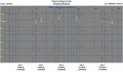
The good news: VERY impressive specifications for efficiency (100dB/metre), distortion, frequency response, impulse response, and headroom.
How much headroom? With a 2.5 kHz 2nd-order LR highpass filter, and powered by a 120-watt amp run into heavy clipping for an hour, no damage or specification change to the diaphragm. With a 200-watt amp run into less severe clipping, the driver delivers 121 dB at one metre, again, with only a 2nd-order filter at 2.5 kHz. THAT's the kind of spec I've been looking for.
Here's the first graph, showing frequency response as measured at 1 meter, with 5 dB/div.
Just got off the phone with Aleksandar Radisavljevic of RAAL, and he's making the double-high version of the 140-15 ribbon tweeter available to us DIY'ers and the prosound studio-monitor builders. The new tweeter is essentially two 140-15's stacked on top of each other with a new faceplate and newly designed foam dampers on the ends.
Let's get the bad news out of the way first: vertical dispersion is about 15 degrees as measured at 1 meter, although the RAAL foam pads help smooth the edges of the vertical polar pattern. The horizontal polar pattern is as wide as the other RAAL models. The other slightly bad news is the 4 ohms impedance - although this is completely resistive and non-reactive.
The good news: VERY impressive specifications for efficiency (100dB/metre), distortion, frequency response, impulse response, and headroom.
How much headroom? With a 2.5 kHz 2nd-order LR highpass filter, and powered by a 120-watt amp run into heavy clipping for an hour, no damage or specification change to the diaphragm. With a 200-watt amp run into less severe clipping, the driver delivers 121 dB at one metre, again, with only a 2nd-order filter at 2.5 kHz. THAT's the kind of spec I've been looking for.
Here's the first graph, showing frequency response as measured at 1 meter, with 5 dB/div.
Attachments
Usual Disclaimer
No financial or business relationship between yrs truly and RAAL, and I expect to pay real money for these, just like you guys. I think we've got a real race between the best of the compression drivers and the new RAALs - choice is good!
P.S. There may be an option of a 3-high (!) RAAL, using response or level shading on the outer pair of tweeters to give a broader vertical polar pattern, and even more power handling.
I also mentioned a Linkwitz-style rear tweeter run 6 dB lower than the front tweeter, as per SL's recommendations. It turns out this would be very easy to do with a single RAAL facing backwards, and the twin ribbons on front, giving an automatic 6 dB front/rear power relation, and the same sonic signature for front and rear drivers.
Re: More Links
Hi Lynn,
just by accident I stumbled over your thread and the link to my paper. I don't know if you are still interested but since it is just a 2-page paper it shouldn't be too much work to translate it to english. Six years ago I only had very limited resources to do the simulation - if you are interested I could redo some of the initial experiments using proper finite element analysis tools.
On a completely different issue - on your website you show some MLSSA measurements - apparently we have a software that can read FRQ- and TIM-files for display and post-proceesing purposes, which allows you to export the diagrams as PNG. Maybe you want to check it out - its called VacsViewer (www.vacsviewer.com) and is available here: http://www.randteam.de/download/dl.php?nav_id=VacsViewer_Download
The Viewer is offered free of charge and identical with the full-featured version (VACS) but lacks the "save project"-feature.
Anyway - if you are interested let me know.
Lynn Olson said:I'd like to quote Rudolf from another discussion:
"Ferekidis has shown that a baffle, which does not exceed 2.2 times the effective driver diameter, works best with regard to minimised edge diffraction. The complete derivation is only available in German:"
http://www.randteam.de/papers_lf/daga_2001-lf.pdf
Rudolf Finke's Dipole-Analysis site is at:
http://www.dipolplus.de/
Wish I could read German! This is interesting stuff. The graphs alone are quite informative.
Hi Lynn,
just by accident I stumbled over your thread and the link to my paper. I don't know if you are still interested but since it is just a 2-page paper it shouldn't be too much work to translate it to english. Six years ago I only had very limited resources to do the simulation - if you are interested I could redo some of the initial experiments using proper finite element analysis tools.
On a completely different issue - on your website you show some MLSSA measurements - apparently we have a software that can read FRQ- and TIM-files for display and post-proceesing purposes, which allows you to export the diagrams as PNG. Maybe you want to check it out - its called VacsViewer (www.vacsviewer.com) and is available here: http://www.randteam.de/download/dl.php?nav_id=VacsViewer_Download
The Viewer is offered free of charge and identical with the full-featured version (VACS) but lacks the "save project"-feature.
Anyway - if you are interested let me know.
Dissing the DCX
Hi
I absolutely agree for the electrolytics in the DCX.
Having done extended modding on the DCX I don't agree about the opamps.
These are all NJM 4580 from New Japan Radio. When biased properly the NJM opamps sound way better than any NE5532 found in many units from ElectroVoice / Dynacord, TC-Electronics and others.
Mackie uses NJM opamps throughout its mixer line for example and there are MANY in daisy chain until the signal leaves the output.
I myself found them working extreme musically in an early Philips CD consumer player and havent been disappointed until now compared to several others from TI, AD, BB and LT and others at up to Euro 10-15.- each.
Actually the DCX is a great unit with some flaws and considering the price a really break through to all and everything that was available before.
Proof that by placing a EV DX38 - having several times the price tag of a DCX and for shure IS a well build pro gear - next to the DCX2496 and I'll bet - after some break in - even with no modification on the DCX you will choose the DCX.
Beside that, the output filter section of the DCX isn't as good as could be. The DA chip – a AK4393 from Asahi Kasei – seems to have not that good reconstruction filter build in as we would like. This results in pretty much HF leakage picked up by the following opamp low pass stage. This issue can NOT be addressed by simply switching to high speed opamp as I have tried even with 1000V/us types but rather by placing an additional PASSIVE LP filter in between.
An other way out, suggested by some people is to replace the AK4393 with the superior AK4395 as a drop in replacement but I haven't proven that by myself.
Several guys have reported very good results by replacing the whole opamp output section with Lundahl transformers.
IF you are willing to spend several times the money for the DCX to its modding, this for sure is a very elegant solution. Keep in mind the restrictions due to the high output impedance of the DA. They will produce considerable more THD and IM when loaded heavily. THD and IM also will be added through the transformers.
By the way biasing is poor throughout the DCX design and you will gain pretty much addressing this. Some further room for improvement can be found in alternatives to the ceramic SMD capacitors used in the signal path and adressing layout issues.....
Greetings
Michael
Hi
I think you're headed in the right direction. The biggest problem with the Behringer DCX is that the op-amps and electrolytic coupling caps are the cheapest possible, basically the same parts quality as used in a Chinese-made Wal-Mart boom box. But fortunately all the analog circuitry of the DCX is on a separate circuit board connected with ribbon wire, and there are aftermarket kits to replace the DCX analog electronics at a modest cost. I'd expect DBX and Rane to sound good right out of the box - both are quality pro brands..
I absolutely agree for the electrolytics in the DCX.
Having done extended modding on the DCX I don't agree about the opamps.
These are all NJM 4580 from New Japan Radio. When biased properly the NJM opamps sound way better than any NE5532 found in many units from ElectroVoice / Dynacord, TC-Electronics and others.
Mackie uses NJM opamps throughout its mixer line for example and there are MANY in daisy chain until the signal leaves the output.
I myself found them working extreme musically in an early Philips CD consumer player and havent been disappointed until now compared to several others from TI, AD, BB and LT and others at up to Euro 10-15.- each.
Actually the DCX is a great unit with some flaws and considering the price a really break through to all and everything that was available before.
Proof that by placing a EV DX38 - having several times the price tag of a DCX and for shure IS a well build pro gear - next to the DCX2496 and I'll bet - after some break in - even with no modification on the DCX you will choose the DCX.
Beside that, the output filter section of the DCX isn't as good as could be. The DA chip – a AK4393 from Asahi Kasei – seems to have not that good reconstruction filter build in as we would like. This results in pretty much HF leakage picked up by the following opamp low pass stage. This issue can NOT be addressed by simply switching to high speed opamp as I have tried even with 1000V/us types but rather by placing an additional PASSIVE LP filter in between.
An other way out, suggested by some people is to replace the AK4393 with the superior AK4395 as a drop in replacement but I haven't proven that by myself.
Several guys have reported very good results by replacing the whole opamp output section with Lundahl transformers.
IF you are willing to spend several times the money for the DCX to its modding, this for sure is a very elegant solution. Keep in mind the restrictions due to the high output impedance of the DA. They will produce considerable more THD and IM when loaded heavily. THD and IM also will be added through the transformers.
By the way biasing is poor throughout the DCX design and you will gain pretty much addressing this. Some further room for improvement can be found in alternatives to the ceramic SMD capacitors used in the signal path and adressing layout issues.....
Greetings
Michael
Yes, Interested in Translation
Yes, I'd like to take you up on the translation. When I went to the European Triode Festival in the winter of 2004, I was surprised at just far along the Germans, and other Europeans, had gone with dipoles. And the notorious problem with Americans, Brits, Ozzies, and New Zealanders is that we only rarely speak other languages.
This gives a one-way diode effect with audio - Germans, French, Italians, Japanese, Chinese read US and UK audio magazines, but research in the non-English languages only slowly (if at all) makes it into the English-speaker audio world. One thing I really like about this site are the lively contributions from Europeans and Asians - the American-dominated sites make for pretty dull reading by comparison.
I'll give the VacsViewer a try - once I get mobile again. The MLSSA system is downstairs in the basement, which might as well be on Mars in terms of personal mobility. At least I'm now allowed to put some weight on my leg, which is building up its strength, getting me closer to the usual left-right-left-right pattern of walking again.
Lampos said:
Hi Lynn,
just by accident I stumbled over your thread and the link to my paper. I don't know if you are still interested but since it is just a 2-page paper it shouldn't be too much work to translate it to english. Six years ago I only had very limited resources to do the simulation - if you are interested I could redo some of the initial experiments using proper finite element analysis tools.
On a completely different issue - on your website you show some MLSSA measurements - apparently we have a software that can read FRQ- and TIM-files for display and post-proceesing purposes, which allows you to export the diagrams as PNG. Maybe you want to check it out - its called VacsViewer (www.vacsviewer.com) and is available here: http://www.randteam.de/download/dl.php?nav_id=VacsViewer_Download
The Viewer is offered free of charge and identical with the full-featured version (VACS) but lacks the "save project"-feature.
Anyway - if you are interested let me know.
Yes, I'd like to take you up on the translation. When I went to the European Triode Festival in the winter of 2004, I was surprised at just far along the Germans, and other Europeans, had gone with dipoles. And the notorious problem with Americans, Brits, Ozzies, and New Zealanders is that we only rarely speak other languages.
This gives a one-way diode effect with audio - Germans, French, Italians, Japanese, Chinese read US and UK audio magazines, but research in the non-English languages only slowly (if at all) makes it into the English-speaker audio world. One thing I really like about this site are the lively contributions from Europeans and Asians - the American-dominated sites make for pretty dull reading by comparison.
I'll give the VacsViewer a try - once I get mobile again. The MLSSA system is downstairs in the basement, which might as well be on Mars in terms of personal mobility. At least I'm now allowed to put some weight on my leg, which is building up its strength, getting me closer to the usual left-right-left-right pattern of walking again.
Improving the DCX
Thanks for the op-amp info. I had thought they were the dreadful multiple 741's on a single chip, the truly miserable 3V/uSec opamp that was the curse of the early Seventies and still with us in low-end audio gear. It sounds like the 4580 is quite a different animal, and a welcome change from the very stale 5532's and 5534's. I imagine by "biasing" you mean the old trick of a pull-down resistor (or current source) to bias the op-amp into Class A.
Since the DCX is so popular - and extremely flexible by any standard - all thoughts on sonic mods are welcome. At the minimum, they offer a really fast way to tune up a system, and with dipoles being such a freaky challenge to measure, this is very useful to all dipole-fans.
mige0 said:Hi
Having done extended modding on the DCX I don't agree about the opamps.
These are all NJM 4580 from New Japan Radio. When biased properly the NJM opamps sound way better than any NE5532 found in many units from ElectroVoice / Dynacord, TC-Electronics and others.
Mackie uses NJM opamps throughout its mixer line for example and there are MANY in daisy chain until the signal leaves the output.
I myself found them working extreme musically in an early Philips CD consumer player and havent been disappointed until now compared to several others from TI, AD, BB and LT and others at up to Euro 10-15.- each.
Greetings
Michael
Thanks for the op-amp info. I had thought they were the dreadful multiple 741's on a single chip, the truly miserable 3V/uSec opamp that was the curse of the early Seventies and still with us in low-end audio gear. It sounds like the 4580 is quite a different animal, and a welcome change from the very stale 5532's and 5534's. I imagine by "biasing" you mean the old trick of a pull-down resistor (or current source) to bias the op-amp into Class A.
Since the DCX is so popular - and extremely flexible by any standard - all thoughts on sonic mods are welcome. At the minimum, they offer a really fast way to tune up a system, and with dipoles being such a freaky challenge to measure, this is very useful to all dipole-fans.
- Home
- Loudspeakers
- Multi-Way
- Beyond the Ariel