"But does it move the end in the process of calculating the CSD? What I've seen is "no". As a matter of fact, CLIO could never show the resolution required from one of our suppliers."
Hello soongsc
Not sure what you mean. It clearly says in the manual that when you run a CSD plot the start and stop times determine the data processed so only the data in the selected time window is processed. Could be when they did an update they changed it?? I have Clio 7.13 running now.
You select a widow and the program runs a CSD for that window. You can trim off the initial delay from the standard 1 meter spacing and then select a point before the first reflection. So you effectively trim both sides. You can move this window anywhere in the measurement and run a CSD plot for that section of the measurement.
As far as resolution the version I have seems just fine. I can enter a time shift value and effectively zoom into the first couple of milliseconds to see what the initial decay looks like if I want more detail.
Rob")
Hello soongsc
Not sure what you mean. It clearly says in the manual that when you run a CSD plot the start and stop times determine the data processed so only the data in the selected time window is processed. Could be when they did an update they changed it?? I have Clio 7.13 running now.
You select a widow and the program runs a CSD for that window. You can trim off the initial delay from the standard 1 meter spacing and then select a point before the first reflection. So you effectively trim both sides. You can move this window anywhere in the measurement and run a CSD plot for that section of the measurement.
As far as resolution the version I have seems just fine. I can enter a time shift value and effectively zoom into the first couple of milliseconds to see what the initial decay looks like if I want more detail.
Rob
Normally the end of the window is not moved in the process of generating the CSD, and it is always placed before the first reflection. Only the beginning of the window is moved. How much it is moved when it generates a slice in the CSD normally depends on the sample time interval. However, if you move the window manually, the different software might operate differently. For example, in SoundEasy, once you have the window width set, if you move the beginning, then the end will move with it, which will cause the end to include the reflection at some point in time. If I remember correctly, PRAXIS moves the beginning and end independently; how CLIO does it, I cannot remember. One thing about CLIO I remember is that we could never get it to show good CSD resolution in the 0.4ms range.Robh3606 said:"But does it move the end in the process of calculating the CSD? What I've seen is "no". As a matter of fact, CLIO could never show the resolution required from one of our suppliers."
Hello soongsc
Not sure what you mean. It clearly says in the manual that when you run a CSD plot the start and stop times determine the data processed so only the data in the selected time window is processed. Could be when they did an update they changed it?? I have Clio 7.13 running now.
You select a widow and the program runs a CSD for that window. You can trim off the initial delay from the standard 1 meter spacing and then select a point before the first reflection. So you effectively trim both sides. You can move this window anywhere in the measurement and run a CSD plot for that section of the measurement.
As far as resolution the version I have seems just fine. I can enter a time shift value and effectively zoom into the first couple of milliseconds to see what the initial decay looks like if I want more detail.
Rob
"For example, in SoundEasy, once you have the window width set, if you move the beginning, then the end will move with it, which will cause the end to include the reflection at some point in time."
OK I see what you are getting at.
"If I remember correctly, PRAXIS moves the beginning and end independently;"
Clio is like Praxis.
"One thing about CLIO I remember is that we could never get it to show good CSD resolution in the 0.4ms range."
OK I don't see why?? You can manualy set a Time Slice widow and use that to Zoom in so to speak. I can set up a 50usec slices and run 30 of them so I see the first 1.5msec in 50usec slices.
Here is an example.
Rob
Attachments
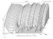
Well, that's still 3 times the time interval for one, and at sampel rate of 96KHz, it should be possible to have a time slice of about 10.4uS. Second, it still samples part of the main impulse. So the hill you see is not exactly starting when the impulse hits zero. This is why it becomes very confusing. Idealy we want to look at how things respond starting from when the main impulse first zeros out.
ScottG said:Completely wrong.
...
I guess basically what I'm saying here is that if you are going to drop an "expert" *opinion* into the discussion, that you should probably read that discussion a little more carefully.
Don't take that xpert attitude to serious. Don't let it bring You into anger. I'm not different from You in that I'm quite convinced that I have to say a thing about the topic. I read Your post.
CSD seems to be a concept not known thoroughly enough to derive conclusions from it. CSD is completely based on the impulse response. The impulse response is completely derived from amplitude/phase over frequency. To make a CSD one needs not more than a frequency response! CSD is a representation of STEADY STATE frequency response of amplitude and phase! Check it out.
I did. That's why I am an "xpert" (just kidding)
Hi,
it does not. Or, in other words, the real - I call it effective - frequency resolution is determined by the length of the unpadded impulse response. The zero-padding (to get a power of 2 for FFT) does only add interpolated samples to the result.
Bye
Baseballbat
john k... said:The FFt length, which is completely unrelated, sets the frequency resolution.
it does not. Or, in other words, the real - I call it effective - frequency resolution is determined by the length of the unpadded impulse response. The zero-padding (to get a power of 2 for FFT) does only add interpolated samples to the result.
Bye
Baseballbat
I'm happy to see that we (most) finally came to a point where the resonances seen in CSD got accepted as such – and also some cevelets in taking CSD measurements were outlined.
In fact - a measurement / processing method that basically relies on infinite duration of sine waves that are processed – isn't particularly designed to show what's happening when they disappear (to cite someone, I highly respect).
Anyway – I'd like to do an experiment.
As I have the tools available to change acoustic IR of a speaker at will by "a simple click" – I'd like to know if there is a benefit we can gain for open baffles from that.
(it also might put some shade of light on any other multi way or line array speakers further on)
What I outlined some postings ago is that I got off axis decay above the first baffle peak (best seen at the 1/3 octave smoothed pix).
My explanation then was that its originating from the fact that I shaped impulse response in a way to integrate the delayed back wave close to ideal with the front wave to get perfect IR at on axis (also shown by measurement).
- Meaning - I added "energy storage" by equalisation.
Now – if I'm right here – we could ask if it might be better *not* to introduce that specific equalisation
- meaning – that we rather accept some impulse smearing on axis in favour to non-added decay off axis.
I simply could try - but really would like to hear your thoughts first.
Michael
mige0 said:
In fact - a measurement / processing method that basically relies on infinite duration of sine waves that are processed – isn't particularly designed to show what's happening when they disappear (to cite someone, I highly respect).
...
Michael
Michael,
Every sine wave is in its own concept lasting forever. It is its very mathematical/physical heart. To describe changes within a spectrum needs example given a Fourier analysis. But this would work on frequencies too, that rely on its infinite duration. Thats the concept of "frequency".
Your conclusion cited above is misleading. As far as the system is linear, there is NO conceptual difference between a steady state and any other state, example given "shut off". This is known for hundreds of years now. It is part of the education of every engineer in Europe ever since.
mige0 said:I'm happy to see that we (most) finally came to a point where the resonances seen in CSD got accepted as such – and also some cevelets in taking CSD measurements were outlined.
That's quite bold. I've shown that effects that are non resonant will make a ridge in the CSD by introducing group delay. Example given different pathlengths in a source (the dipole baffle, righty right). You didn't differentiate such from true resonances! Which made people accept Your claims then?
But - I give up not to make that fool out of me ...
Robh3606 said:"For example, in SoundEasy, once you have the window width set, if you move the beginning, then the end will move with it, which will cause the end to include the reflection at some point in time."
OK I see what you are getting at.
"If I remember correctly, PRAXIS moves the beginning and end independently;"
Clio is like Praxis.
I like systems that have independent time markers, since there are times when some adjustment is warrented. Once set, though, the window is fixed during any post processing for most systems. Soongsc is correct about that. I can't see how a fully sliding window would be useful in typical acoustic measurements.
One thing to note is that some software, MLSSA, LAUD and some others (not Praxis I think), indicate that loss of resolution in the successive CSD slices due to window length reduction by "wrapping" it so-to-speak. The low end is cut off in the display, example below.
Another often overlooked issue is the vertical scale. A lot of software by default sets this to less than 30db maximum and I've seen 24db used. I like to set it at 40db as seen in graph above. Some resonances get buried under the "floor" if the scale is reduced like this.
That's part of why it's difficult to compare measurements from different tests, aside from all of the other confounding factors. Simply using a window doesn't make them all equal. CSDs are too prone to misinterpretation for several of reasons. To me they are of limited use.
Dave
xpert said:
I've shown that effects that are non resonant will make a ridge in the CSD by introducing group delay. Example given different pathlengths in a source (the dipole baffle, righty right). You didn't differentiate such from true resonances!
Isn´t resonance in itself a special manifestation of group delay? Like comb filtering with a constant 360° phase delay at the resonant frequency? If that would be the case, we would have gone full circle: Everything in a CSD would be group delay. Or: Every group delay could be interpreted as some special expression of resonance.
Baseballbat said:Hi,
it does not. Or, in other words, the real - I call it effective - frequency resolution is determined by the length of the unpadded impulse response. The zero-padding (to get a power of 2 for FFT) does only add interpolated samples to the result.
Bye
Baseballbat
Yes, in the pure mathematical definition zero padding is ideal interpolation. However, the interpolation is not necessarily inaccurate or an untrue representation of increased resolution. The application must be considered. This implies that to increase frequency resolution from X Hz to X/2 Hz requires that the length of the measured sample is doubled regardless of the length of the impulse. That is not correct, though commonly accepted. Here is a quote from an AES paper by Eric Benjamin,
"Although the frequency resolution and the length of the time window are tied together in many measurement schemes, there is no reason why that needs necessarily to be so. A long transformation can be used to get a narrow frequency resolution measurement from a short analysis window, as long as all the spectral information about the transfer functions is included within that window."
In other words, the spectral information defining the transfer function is limited to that contained within the window while the frequency resolution is set by the length of the FFt.
If the impulse of a system goes to zero (without windowing) within Y msec does that mean the lowest frequency we can obtain and corresponding frequency resolution is 1/Y Hz? If the impulse goes to zero in Y msec is there any difference between sampling the signal to 16Y or zero padding a sample of length y msec to 16 y msec? If extending the length of the measured sample does not add any additional spectral information to the impulse because it is zero, then zero padding yields an identical result, with the same increased resolution.
If we measure at 48K Hz it makes no difference if we have a sample length of 32768 or a sample length of 4096 zero padded to 32768 if the window is 5 msec long. The FFt of both will be identical. The window type and length set the spectral content of the impulse. The windowing throws away spectral content and "pads" the measured impulse with zeros beyond the window's end. The length of the FFt sets the resolution. So it you prefer to consider the zero padded result interpolated, that is fine. But the result is identical to the unpadded case because the widowing supersedes this.
xpert said:
But - I give up not to make that fool out of me ...
Excellent !

- but wrong again!
You already have made a fool out of you by your claim I have proven you wrong.
And not even exactly by that - I do mistakes as well - no need to be perfect - not even in the public (around here) - but I also don't come along with the "Mr. Xpert" attitude - meaning - I accept to not being perfect and let others know - even more so if I *am* wrong occasionally.
By by
Michael
xpert said:
Don't take that xpert attitude to serious. Don't let it bring You into anger. I'm not different from You in that I'm quite convinced that I have to say a thing about the topic. I read Your post.
No anger.

(the
emoticon was there to try and help identify that, and that the "expert" comment was mild play on words.)BTW, I do understand what the CSD is, and how it can be used and misused. IMO it is (generally) significantly more useful than looking at the impulse response for short time duration. An energy-time curve (specific freq.) is another useful tool as well with respect to decay performance, particularly for "dialing-down" further into problem areas that might be detected with a CSD.
Hi,
this is correct, and I agree that interpolation must not be completely wrong. But your example has nothing to do with the reality of speaker measurements. In speaker measurements, you have information up to (e. g.) 32k samples, cut it down to 5ms and then extend the data by interpolation up to 32k bins. See the difference? Of course, this may work at high frequencies, where the frequency resolution is comparatively small, but at lower frequencies you have big problems. As I said, 5ms gives you reliable results above ~400Hz, not 200Hz as in theory. Is that what you want?
I prefer a long time window around 100ms, and then use strong smoothing. 1/3 or even 1/1, depends on the unsmoothed curve. Another method is to use the peak level in a burst decay. This gives you also phase information, the frequency resolution depends on the bandwidth of the used wavelet (usual 1/6 or 1/3 octave).
Bye
Baseballbatboy
john k... said:If we measure at 48K Hz it makes no difference if we have a sample length of 32768 or a sample length of 4096 zero padded to 32768 if the window is 5 msec long. The FFt of both will be identical. The window type and length set the spectral content of the impulse. The windowing throws away spectral content and "pads" the measured impulse with zeros beyond the window's end. The length of the FFt sets the resolution. So it you prefer to consider the zero padded result interpolated, that is fine. But the result is identical to the unpadded case because the widowing supersedes this.
this is correct, and I agree that interpolation must not be completely wrong. But your example has nothing to do with the reality of speaker measurements. In speaker measurements, you have information up to (e. g.) 32k samples, cut it down to 5ms and then extend the data by interpolation up to 32k bins. See the difference? Of course, this may work at high frequencies, where the frequency resolution is comparatively small, but at lower frequencies you have big problems. As I said, 5ms gives you reliable results above ~400Hz, not 200Hz as in theory. Is that what you want?
I prefer a long time window around 100ms, and then use strong smoothing. 1/3 or even 1/1, depends on the unsmoothed curve. Another method is to use the peak level in a burst decay. This gives you also phase information, the frequency resolution depends on the bandwidth of the used wavelet (usual 1/6 or 1/3 octave).
Bye
Baseballbatboy
ScottG said:Note however that shorting rings (emphasis on plural) is considerably less effective than a counter wound coil a' la 18 Sound "Active Impedance".)
The most effective method for reducing and linearizing inductance and lowering distortion is a full sleeve over the pole, or getting rid of electrical conductivity in the pole. The problem with AIC is that you are now adding more heat to the motor. You take away any ability to sink heat into the pole. You've instantly lost about 2/3 of the heatsinking of the coil and at the same time add more heat to the motor. Take a look through their own paper which shows that the shorting ring in the right place is more effective. A full sleeve of adequate thickness is even more so effective.
The "slow sound" is principally NOT due to inductance levels, but rather a lack of efficiency and increased moving mass. There are any number of drivers that bear this out.
Take a look at the impulse responses measured with added mass to a driver. The magnitude of the impulse decreases as you are losing efficiency. However, the rise time and decay time will not change. This shows that added mass in itself is not the issue.
Now look at a driver with a shorting ring and then again with the shorting ring removed. With the shorting ring removed, both rise and decay time are increased.
Now, your comment that high moving mass drivers sound "slow" does have some merit, but it's important to see why. If you take a driver and increase cone mass it has no effect on impulse response time. However if you add more mass to the VC which is at the same time increasing inductance, increasing flux modulation, etc this is where the issue comes from. Most typically higher mass drivers have larger coils and have higher inductance.
"Acceleration Factor" in the context of loudspeakers is simply an industry term specific to loudspeaker drivers. And yes, it does seem to have a rather good correlation with a driver sounding more or less "slow".
If you include current into the acceleration factor, then it does definitely give a good correlation. Current again is determined greatly by inductance. Many people look at Bl/Mms. This means nothing as you aren't taking into account the resistance of the coil. Take a DVC driver with 100gram Mms. Say with coils in parallel
(4ohm)Bl is 10 and with coils in series(16ohm) Bl is 20. Looking at Bl/Mms, the ratio doubles, although there is nothing different about the acceleration factor of the driver. It will sound exactly the same. However, change the inductance and there is a huge difference.
John
John_E_Janowitz said:
The most effective method for reducing and linearizing inductance and lowering distortion is a full sleeve over the pole, or getting rid of electrical conductivity in the pole.
John - agreed even if we disagree on what extent is necessary.
John_E_Janowitz said:
If you take a driver and increase cone mass it has no effect on impulse response time.
John
I had trouble following your comments (maybe I'm "slow"
), but I'm fairly sure that the statement above can't be true. Could you explain what you intended here.ScottG said:
No anger.
... decay performance, particularly for "dialing-down" further into problem areas that might be detected with a CSD.
Group Delay:
http://www.jobst-audio.de/Entwicklungen/mt-1214/mt-1214_gd.jpg
Amplitude:
http://www.jobst-audio.de/Entwicklungen/mt-1214/mt-1214_fgang2.jpg
CSD:
http://www.jobst-audio.de/Entwicklungen/mt-1214/mt-1214_csd.jpg
The speaker has a little problem around 7kHz which can be seen from either amplitude or group delay. As You say in American English, CSD is a no brainer. In this case it tells less than the first two. Most probably it is some path difference in the horn/driver combination or an interference from ridges reflections on the baffle. What does the CSD help here?
People simply don't understand that CSD is not dynamic data. It is calculated completely from the STEADY STATE frequency response. Take that! What is it worth?
by
by the way perpetuated: reflection and path difference are NO resonances!
xpert said:
People simply don't understand that CSD is not dynamic data. It is calculated completely from the STEADY STATE frequency response. Take that! What is it worth?
Huh? When I saw my first FFT's and CSD's at KEF in 1975 they were calculated directly from a single gigantic 200-watt impulse fed to the speaker. The impulse data was captured DIRECTLY from the digitizer as it came into the computer. No steady-state there. To lower the noise floor, they'd then average a series of impulse measurements, but that meant adding a series of time-domain measurements directly on top of each other, not a conversion into the frequency domain.
FFT's and CSD's were calculated from the raw time-domain data, not the other way around. As a long-time user of 500 and 7000-series Tektronix scopes and spectrum analyzers, I know the difference between real-world time measurements and computed frequency-domain measurements. What you see on the screen of a scope is not "computed" in any way - scopes are nothing more than vertical amplifiers that show the waveshape directly on a scanned, non-storage display. If you see the trace wiggle on a scope, you can pretty sure something really happened to the electrical signal.
I'm not saying that frequency domain measurements aren't useful, but they are computed from the real world of the time domain. As computations, you have to intelligently select the appropriate algorithm to transform the domains, and be aware of what artifacts are generated by the choice of algorithm. People are so comfortable with computers and software they forget that brickwall lowpass filters that ring in the time domain, ADC's running at low sampling rates, and choice of algorithm do not have a neutral interpretation of the raw electrical data.
Lynn Olson said:
Huh? When I saw my first FFT's and CSD's at KEF in 1975 ... time domain. ... you have to intelligently select the appropriate algorithm to transform the domains ... ADC's running at low sampling rates, and choice of algorithm do not have a neutral interpretation of the raw electrical data.
Today CSD is calculated from a normalised impulse response. The normalised IR is too the basis for amplitude and phase response calculations. Because the said transformations are simply calculations there is no more information in one than in the other. How CSD is of less readibility can be seen in my last post above.
OK, now I'm really confused. In your own words, the normalized impulse response - which, by definition, is in the time domain - is used to calculate the amplitude and phase response. Ipso facto, time domain is the starting point, and further calculations yield frequency, phase, and non-minimum phase information. What confuses me is that you stated in a previous post that the CSD is calculated from STEADY STATE (your emphasis) frequency response. So what is it? Is the CSD calculated from the impulse response, or not?
Since loudspeakers are complex electromechanical devices, minimum-phase operation cannot be assumed - they are not amplifiers, after all, and have non-minimum-phase crossovers, regions of driver breakup, diffraction off the cabinet edges, not to mention nonlinear distortion at all power levels. All of these defects are audible and degrade the sound - the point of any measurement is to find correlations between subjective impressions and possible methods to improve the loudspeaker.
Since loudspeakers are complex electromechanical devices, minimum-phase operation cannot be assumed - they are not amplifiers, after all, and have non-minimum-phase crossovers, regions of driver breakup, diffraction off the cabinet edges, not to mention nonlinear distortion at all power levels. All of these defects are audible and degrade the sound - the point of any measurement is to find correlations between subjective impressions and possible methods to improve the loudspeaker.
- Home
- Loudspeakers
- Multi-Way
- Beyond the Ariel