These may be of interest.
Discussion of stored energy in drivers.
Stored energy in crossovers.
Impulse response of dipoles with emphasis on the mid frequency range, baffle and source type.
Discussion of stored energy in drivers.
Stored energy in crossovers.
Impulse response of dipoles with emphasis on the mid frequency range, baffle and source type.
Lynn Olson said:'''a scaled-up Fonken seems like a good candidate for the 414, ...
AKA "Le Petit Onken".
Attachments
What I like about the Fonken are 45-degree slant sides, similar to the RCA LC-1A Harry F. Olson design. It wouldn't be rocket science to re-calculate the box volume to comply with a modern minimum-group-delay alignment (tending towards a Bessel/Gaussian highpass characteristic), and use slant sides a la Fonken/LC-1A practice.
The Bessel/Gaussian highpass function isn't all that exotic - my first subwoofer in 1979 used that alignment - and yes, they do sound better, mostly for the simple reason it is less sensitive to driver parameter shifts than the more common alignments. Conventional 4th-order highpass filters (vented boxes) are quite touchy about parameter shifts, and low-Q alignments can help quite a bit. If your simulation software has a group-delay visualization feature, I'd certainly use it. Minimizing group-delay variation is a lot more important than trying to chase the last few Hz out of a given driver.
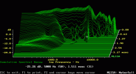
JohnK, thanks for the links. In my usual contrarian way, I mostly agree but not 100%. I've seen some very unusual behavior in the waterfall displays that makes me doubt how linear drivers are in the breakup region. (By "linear" I mean capable of being modeled by minimum-phase RLC networks).
Here's an example from Page Five of the MLSSA Gallery (shown below). It's an Eton 4-203 showing what can only described as perverse behavior - a resonance that starts at 4.5 kHz at T=0 and slides upwards to 5 kHz by T=1.5 mSec. No conceivable RLC network can do this; it takes a mechanical device - like a piano or a driver in breakup - to have resonances behave in this way.
This was a highly regarded driver back in its day. But how would you design a notch filter around a sliding resonance? If it were tuned to the starting point, 4.5 kHz, the resonance would "fade in" after time, an extremely unnatural result. If the filter were tuned to 5 kHz, the resonance would fade in and out, like a very fast shortwave broadcast with lots of multipath skip.
Other breakup behavior, for lack of a better word, looks chaotic, and does not respond to in-band equalization. The tip-off to chaotic behavior is when the waterfall looks radically different when the microphone is moved a few inches to one side or the other. A lot of the "exotic" rigid cone materials have trouble with this - I've seen it with Kevlar, carbon-fiber, and the various composites that get thrown into paper cones.
The Bessel/Gaussian highpass function isn't all that exotic - my first subwoofer in 1979 used that alignment - and yes, they do sound better, mostly for the simple reason it is less sensitive to driver parameter shifts than the more common alignments. Conventional 4th-order highpass filters (vented boxes) are quite touchy about parameter shifts, and low-Q alignments can help quite a bit. If your simulation software has a group-delay visualization feature, I'd certainly use it. Minimizing group-delay variation is a lot more important than trying to chase the last few Hz out of a given driver.
JohnK, thanks for the links. In my usual contrarian way, I mostly agree but not 100%. I've seen some very unusual behavior in the waterfall displays that makes me doubt how linear drivers are in the breakup region. (By "linear" I mean capable of being modeled by minimum-phase RLC networks).
Here's an example from Page Five of the MLSSA Gallery (shown below). It's an Eton 4-203 showing what can only described as perverse behavior - a resonance that starts at 4.5 kHz at T=0 and slides upwards to 5 kHz by T=1.5 mSec. No conceivable RLC network can do this; it takes a mechanical device - like a piano or a driver in breakup - to have resonances behave in this way.
This was a highly regarded driver back in its day. But how would you design a notch filter around a sliding resonance? If it were tuned to the starting point, 4.5 kHz, the resonance would "fade in" after time, an extremely unnatural result. If the filter were tuned to 5 kHz, the resonance would fade in and out, like a very fast shortwave broadcast with lots of multipath skip.
Other breakup behavior, for lack of a better word, looks chaotic, and does not respond to in-band equalization. The tip-off to chaotic behavior is when the waterfall looks radically different when the microphone is moved a few inches to one side or the other. A lot of the "exotic" rigid cone materials have trouble with this - I've seen it with Kevlar, carbon-fiber, and the various composites that get thrown into paper cones.
Attachments
Lynn Olson said:The Bessel/Gaussian highpass function isn't all that exotic - my first subwoofer in 1979 used that alignment - and yes, they do sound better, mostly for the simple reason it is less sensitive to driver parameter shifts than the more common alignments.
I don't know if i hit bessel with the Fonken, but one of the goals was to get a bass alignment that was less sensitive to parameter shifts. We've been able to extend the success we had with the Fonken to a whole range of boxes.
dave
planet10 said:
I don't know if i hit bessel with the Fonken, but one of the goals was to get a bass alignment that was less sensitive to parameter shifts. We've been able to extend the success we had with the Fonken to a whole range of boxes.
dave
You've hit it, or are very close. Congratulations. The insensitivity to parameter shifts means the inherent 2-pole filters within the 4th-order highpass function are low-Q. If they had high-Q elements you'd be back to conventional alignments, with their notorious sensitivity to driver parameter shifts.
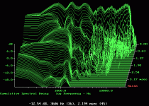
Continuing the previous post, here's a pix of some high-end speaker (costing more than $7,500 a pair) I took some years ago. I don't remember its name, but it was one of $tereophile's Class A or Class B favorites, for what it's worth. These curves, by any definition, are pretty bad. The frequency response (as seen at the rear of the graph), is not good, and the waterfall is pretty gross as well. I would not expect this speaker to have low coloration, no matter what the reviewers said.
Attachments
No idea. I just fiddled around with various alignments until the group-delay looked smooth around the F3 region. I'd like to know if there is software that has group-delay optimization - I haven't seen it yet, but there's lots out there I don't know about.
One alignment I avoid is the Extended Bass Shelf - the ones I've seen have not one, but TWO group-delay bumps, one at the F3 corner and a higher one at the sometimes fairly abrupt shelf-transition frequency.
The nasty thing about LF group-delay variation is the physical number is very large - an apparent front-to-back shift of many feet in the span of a few Hz. Is it audible? People have been wrangling about this for decades - you'll see AES papers written in the 1970's that argue the merits one way or the other. Recordings have huge phase shifts at LF, but these are typically pretty smooth, unlike the sharp highpass characteristics of vented loudspeakers.
By contrast, HF group-delay variation isn't pretty to look on a graph, but the physical numbers might be very small - an inch or less. Maybe it's audible, maybe it's not. Musicians usually wriggle around more than that when they're performing.
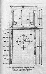
Altec Onken / RCA LC-1A
Dave, why not post or link the dims here for an Onken / RCA LC-1A with the Altec 414 driver for our digestion & DIY and we can proto some cabs for testing...or do you have a mature product availible for this driver & or plan to market one in the near future?
planet10 said:
I don't know if i hit bessel with the Fonken, but one of the goals was to get a bass alignment that was less sensitive to parameter shifts. We've been able to extend the success we had with the Fonken to a whole range of boxes.
dave
Dave, why not post or link the dims here for an Onken / RCA LC-1A with the Altec 414 driver for our digestion & DIY and we can proto some cabs for testing...or do you have a mature product availible for this driver & or plan to market one in the near future?
Re: Altec Onken / RCA LC-1A
Unfortunately i have little interest in this driver and at least a solid month of designs & drawings in the queue already. I have discussed the philosopy behind the Fonken design in at least a couple threads... probably the most recent in a thread started by Bigun.
dave
JoMoCo said:
Dave, why not post or link the dims here for an Onken / RCA LC-1A with the Altec 414 driver for our digestion & DIY and we can proto some cabs for testing...or do you have a mature product availible for this driver & or plan to market one in the near future?
Unfortunately i have little interest in this driver and at least a solid month of designs & drawings in the queue already. I have discussed the philosopy behind the Fonken design in at least a couple threads... probably the most recent in a thread started by Bigun.
dave
On the subject of the 3/8" cotton from Bonded Logic (Ultra Touch Radiant Barrier), you can purchase it from JC Whitney, Summit Racing, Home Depot (web only), and in a few select areas Echo Haus (an environmentally friendly home building supply).
The Ultra Touch Radiant Barrier cotton is quite a bit denser than the Ultra Touch home insulation. The Ultra Touch Radiant Barrier has a foil based radiant insulation facing on one side. The foil peels off easily if you don't want to use the foil. To peel the foil off without tearing the cotton you pull the foil back across the foil face so the foil makes a sharp 180 degree turn as it pulls free.
I think in applications where you want to glue the cotton to a surface like the inside of the speaker basket frame the foil will make the job easier.
The 3/8" insulation is on the thick side, almost 1/2" thick after handling.
The 3 1/2" building insulation is actually more like 2" thick.
Gary
P.S.
I'm in the process of moving my web page. New address:
http://www.pimmlabs.com
Thanx Gary,
Don't know if iany of those are on this side of the border. The Canadian distrib is not far away (but on the mainland)
I suspected as much. There is one spot on our cabs (the holey brace) where flow thru is important.
That the 3/8" fluffs out to 1/2" is a bonus. The piece of 3.5" i have measures 2.75" thick.
dave
Gary P said:On the subject of the 3/8" cotton from Bonded Logic (Ultra Touch Radiant Barrier), you can purchase it from JC Whitney, Summit Racing, Home Depot (web only), and in a few select areas Echo Haus (an environmentally friendly home building supply).
Don't know if iany of those are on this side of the border. The Canadian distrib is not far away (but on the mainland)
I think in applications where you want to glue the cotton to a surface like the inside of the speaker basket frame the foil will make the job easier.
I suspected as much. There is one spot on our cabs (the holey brace) where flow thru is important.
The 3/8" insulation is on the thick side, almost 1/2" thick after handling.
The 3 1/2" building insulation is actually more like 2" thick.
That the 3/8" fluffs out to 1/2" is a bonus. The piece of 3.5" i have measures 2.75" thick.
dave
I am quite interested whether you have tried to measure this same driver in a larger room with a longer window.Lynn Olson said:
...
Here's an example from Page Five of the MLSSA Gallery (shown below). It's an Eton 4-203 showing what can only described as perverse behavior - a resonance that starts at 4.5 kHz at T=0 and slides upwards to 5 kHz by T=1.5 mSec. No conceivable RLC network can do this; it takes a mechanical device - like a piano or a driver in breakup - to have resonances behave in this way.
This was a highly regarded driver back in its day. But how would you design a notch filter around a sliding resonance? If it were tuned to the starting point, 4.5 kHz, the resonance would "fade in" after time, an extremely unnatural result. If the filter were tuned to 5 kHz, the resonance would fade in and out, like a very fast shortwave broadcast with lots of multipath skip.
...
Lynn Olson said:.... perverse behavior - a resonance that starts at 4.5 kHz at T=0 and slides upwards to 5 kHz ...
Hmmmm.... perverse indeed! Puts me in mind of a funny, small, Chinese gong some guys I toured with had.
It was funny, because when struck, it made a pooiiIIING! sound. The pitch went up! But how? Never could figure that out. Like your sliding resonance, but over an octave, maybe.
A cool sound in a gong, maybe not so cool in a driver.

Hi Lynn,
No argument that if the driver isn't fundamentally a linear device then linear eq won't solve the problems. But the "walking" of the resonances in the CSD don't necessarily mean it is not a linear device. The thing that must be remembered is that when we look at a water fall we are not looking at the decay of a single resonance. We are observing the behavior of a system that can have many resonances all decaying at different rates. Additionally, when two or more resonances are closely spaced we may the summed acoustic output can result in beats giving the appearance that resonances decay below a given level and then reappear.
I would agree that, particularly the second driver you show would not be my choice for a high quality system (and unfortunately it looks a lot like the response of many so called full rage drivers). We are always better off starting with smooth behavior. But the CSD for that driver doesn't imply that the driver is not dominantly linear. This is where digital filtering can be very useful, even if the final objective is an analog crossover (active or passive). With digital filtering we can setup a test with driver and mic at a fixed position, take a measurement of the raw SPL, define the acoustic target the driver will have to meet in the proposed application, digitally filter the driver to that response, and remeasure. Then as I did on my web page, compare the CSD (or any other processing of the impulse) to the CSD of the ideal response. This will give us a good ideal of how "linear" the driver is in the range required for the proposed design. We can then proceed to evaluate the driver through other nonlinear distortion testing.
On other thing, if you look at the CSD's on my web page at the lower frequency range (200 to 800 Hz) you can see there is some walking. However these is no such walking in the eq'ed responses.
john k... said:Hi Lynn,
.....Additionally, when two or more resonances are closely spaced we may the summed acoustic output can result in beats giving the appearance that resonances decay below a given level and then reappear....
Like this one at slightly below 200Hz.
An externally hosted image should be here but it was not working when we last tested it.
An externally hosted image should be here but it was not working when we last tested it.
- to me it looks like energy swapping between the two very closely spaced frequencies.
Best seen in the colored sonogram (top view of the CSD) - in contrary to the straight line for the resonance around 350Hz
If you look at the structure in CSD left from 200Hz - there is also a cyclic come and go during decay -looking like fences each 20ms or so
Its take from an enclosure - but where does a speaker end and the enclosure start??
Its all connected by air - volume (mass and suspension) and radiation.
Michael
Very interesting indeed! I always suspected that the gong with the rising pitch actually had the low harmonics decay fast, progressively leaving the higher ones - thus making it sound as though the pitch went up.
I now see that driver can do the same thing, but to a much lesser degree.
Having heard people say that a certain driver "gets the pitch right" makes me wonder is this is part of what's going on.
I now see that driver can do the same thing, but to a much lesser degree.
Having heard people say that a certain driver "gets the pitch right" makes me wonder is this is part of what's going on.
panomaniac said:Very interesting indeed! I always suspected that the gong with the rising pitch actually had the low harmonics decay fast, progressively leaving the higher ones - thus making it sound as though the pitch went up.
I now see that driver can do the same thing, but to a much lesser degree.
....
below an example that possibly could illustrate just that (again driver in enclosure):
An externally hosted image should be here but it was not working when we last tested it.
An externally hosted image should be here but it was not working when we last tested it.
compare the resonace at slightly below 200Hz with the one at roughly 300Hz.
You'll notice that stored energy at 300Hz initially starts lower in SPL but has *much* less decay than the resonance at slightly below 200Hz.
After the 37,76ms shown, the ~200Hz SPL already has dropped to half the SPL level of the 300Hz resonance
Not sure however that masking effects due to different decay times are the main reason for the behaviour of your gong example.
Closely listen to the pitch when you pluck the guitar - the tone clearly turns higher during decay.
Its more form the nonlinearity of the string at different tension (at excursion) I guess.
If the same happens with the spider of a speaker the main resonance would shift like in Lynn's example.
The decay shift form the Eton speaker must have an other reason IMO, as its harly dominated by spider nonlinearity at that high frequencies.
Michael
- Home
- Loudspeakers
- Multi-Way
- Beyond the Ariel