Hello Mr. Olson,
Being the fact that for now it seems that this thread is a little on stand-by, I'll indulge myself with an off-topic.
Did you have the chance to listen to the solid state Tabor amp Gary Pimm developed? How do you compare it to your own Karna. If not the solid state version, how do you judge the sound of penthode vs. triode, keeping in mind that both are (Karna and Tabor) cuting edge in tube amplifier design.
Also, is it possible to contact Mr. Pimm? I couldn't find any contact details on his site..
Thank you!
Gary and I have done extensive comparisons of his amp and the Karna, since he built the Karna and also did the latest mods on them. Before I collected them and drove the Karna's off to Colorado (a 1500-mile drive), we spent most of a day auditioning them on Gary Pimm's very good system (better than nearly anything at the latest Portland VSAC, according to Bud Purvine).
I can't speak for Gary, so I won't try. Here are my impressions of the Karna compared to the GPimm amplifier as of a couple of years ago - Gary tells me they have moved ahead substantially since then.
Both sound surprisingly alike despite radically different topologies - but both share a common Tektronix heritage of instrumentation-style grounding, RF/EMI control, a minimum of high-order distortion products, and very high speed circuitry that avoids slewing at any frequency below 500 kHz. This gives both of them significantly more transparent sound than any commercial amplifier I am aware of - and I think that's due to superior driver design with very low distortion and no switching artifacts in the output stage.
Where they part company - and this takes a direct A/B comparison on the same system - is a somewhat different tonality. The Karna has a mild amount of 45 and 300B "Technicolor" sound, although not laid on with a trowel as in a typical 300B SET design, and a very large and spacious ambient impression - more so than any other amplifier I've heard. The GPimm amplifier is a little cooler, a bit more cerebral, but Gary Pimm has swapped around some key aspects of the design to make it more vivid-sounding - the substitution of the Bud Purvine interstages for the previous Lundahls has made a significant improvement in just that area. So the two amps might even sound closer than before.
One unresolved aspect of the Karna is an annoying variability in the sound from hour to hour - it can range from pretty good commercial-grade to out-of-this-world and transcendently beautiful. I have traced this to different levels of AC line-noise contaminating the AC filament supply, but building a good-sounding DC supply is non-trivial. A generic 3-pin regulator DC supply grossly degrades the overall sound of the amplifier - I know this from personal experience with the Amity amplifier. Gary Pimm built a one of the most exotic DC supply I've ever seen for his previous 300B SET amplifier, and found that a battery supply still sounded better on direct A/B comparison.
One stop-gap solution for the purity of the AC supply is using the Monarchy AC regenerator, which generates a pure sinewave at 100~120VAC, and can be used to power the filaments alone (total filament and heater consumption of two channels is around 60~80 watts, well within the Monarchy's capabilities). I borrowed a Monarchy and confirmed that clearing up the AC filament supply made a major improvement to the Karna amplifier, and completely removed the variability of the sound. It turns out the filament of the DHT tubes sound best within quite a narrow voltage range, while a similar variation in B+ voltage has almost no effect on the sound.
The surprising thing about the GPimm amplifier is the pentode and MOSFET versions sound almost identical - but the MOSFETs are basically operated as super pentodes, and are kept well within Class A operation. So the MOSFET version is no smaller, since the MOSFETs require the very large heatsinks that true (thermal) Class A transistor amplifiers always require.
Gary Pimm has been thinking about a commercial version of his amplifier for some years now, but the unfortunate problem is that transistor amp buyers have degraded tastes compared to people who buy 45, 2A3, and 300B amplifiers. The DHT crowd are into beauty and the highest levels of refinement, and will build exotic ultra-efficient speakers to get there. The transistor buyers, by comparison, are all about lots of watts, even if they won't admit it in public. Many transistor amp buyers are still into the illusion that hundreds of watts, a heavy NC-milled front panel, a famous name, and an astronomical price are what make an amplifier good.
The market for a superlative, world-class 20~30 watt transistor amplifier is almost nonexistent, while the market for 3 to 20 watt DHT amplifiers is robust and growing. I wish there were a serious market for low-powered transistor amplifiers of the highest quality, but I really don't see one, and transistor amplifiers have been around for nearly half a century now. That transistor amp buyers are still falling for pseudo-Class-A scams speaks volumes about the level of knowledge in the market.
I've told Gary that maybe he should commercialize the pentode version, not for any technical reason, but just due to the different markets. Vacuum-tube amp buyers will pay good money for a top-quality Class A amplifier of moderate power, while transistor-amp buyers won't.
The Karna? Well, I was thinking about a commercial version a couple of years ago (I still get the occasional inquiry), but I really don't want to get into manufacturing, parts stocking for inventory, the substantial financial investment for start-up capitalization, attendance at the very expensive trade shows, and the whole rest of the manufacturing thing.
The raw parts cost of the Karna is about $4,000 to $5,000, the electrical design isn't quite finished yet, and it really needs an entirely new mechanical design before it could be put into production. I'm retired, and the prospect of sinking $50,000 to $100,000 into an uncertain venture is not very appealing.
Thank you for your reply!
If you look at the First Watt project Mr. Pass initiated for some years now, it seems that a market sector just might be educated in word-class, medium power amplifiers. His F1-F5 projects brought him a great deal of recognition from the audio market, and he created an image of constantly decreasing the gap between high quality DHT and low power solid state designs.
The market for a superlative, world-class 20~30 watt transistor amplifier is almost nonexistent, while the market for 3 to 20 watt DHT amplifiers is robust and growing. I wish there were a serious market for low-powered transistor amplifiers of the highest quality, but I really don't see one, and transistor amplifiers have been around for nearly half a century now. That transistor amp buyers are still falling for pseudo-Class-A scams speaks volumes about the level of knowledge in the market.
If you look at the First Watt project Mr. Pass initiated for some years now, it seems that a market sector just might be educated in word-class, medium power amplifiers. His F1-F5 projects brought him a great deal of recognition from the audio market, and he created an image of constantly decreasing the gap between high quality DHT and low power solid state designs.
Indeed. The growing tube amp market has also increased the market for efficient loudspeakers. Often single driver and high efficiency. And this in turn has created a market for superlative world class low power amps such as those made by Nelson Pass.If you look at the First Watt project Mr. Pass initiated for some years now, it seems that a market sector just might be educated in word-class, medium power amplifiers. His F1-F5 projects brought him a great deal of recognition from the audio market, and he created an image of constantly decreasing the gap between high quality DHT and low power solid state designs.
Well, I hope Nelson's designs do indeed increase the quality-oriented market for moderate-power transistor amps. It's those doggone sliding-bias amps that keep muddying the waters of Class AB and true, thermal Class A amplifiers.
It's a lot cheaper to twiddle with the bias circuit of an existing high-power Class AB amplifier - that's only a few inexpensive control transistors, less than a dollar's worth of extra parts - than build an amplifier from scratch that is inherently inefficient, runs hot, and demands a large power transformer and an extremely large heatsink (relative to the watts output).
The Class A versus Class AB distinction looks a little different from the perspective of the tube world, since the plate of the tube can run at far higher temperatures than the die of the transistor. For example, a good big tube like a VAIC/Kron/Emission Labs VV52 or a KT88/6550 is rated at a plate dissipation of 50~70 watts, and can be run conservatively at 40 watts quiescent. A stereo amplifier using push-pull pairs will therefore dissipate 160 watts from the plates of all four tubes - indeed, that is the steady-state dissipation of the Amity and Karna amplifiers.
But a heat sink that can dissipate 160 watts while keeping a MOSFET or bipolar transistor dies at acceptable temperatures (50C or less) must be actively fan-cooled or truly gigantic - several feet long.
Steady-state dissipation of 160 watts from 4 power tubes in no big deal, and has been common since the late Fifties for high-quality stereo tube amps. But a steady-state dissipation of 160 watts from a transistor amplifier is quite extraordinary, due to the number of transistors, possible fan-cooling, and size and cost requirements for the heat-sink.
One nasty drawback of fan cooling is the potential for fan failure, which fairly quickly destroys the entire output section of the amplifier, and even poses a fire hazard. So that in turn demands yet another complex circuit to dynamically sense fan status and heat-sink temperature, and gently shut down the entire amplifier if the bearing of the fan decides to take a vacation. After a while, the start-up, shut-down, DC-offset-detect, thermal-management, and protection circuitry becomes more complex than the actual audio amplifier - and if a single part in the "protection" circuitry fails, it takes the amplifier (and the speakers) with it.
Thus there has always been market pressure for transistor amp manufacturers to try and squeeze a quart of out of pint pot, and come up with many different sliding-bias schemes and marketing them as "Class A". Thirty years of running this scam has muddied the waters almost beyond recognition, and has seriously limited and confused the market for a genuine, low-power, true Class A transistor amplifier - there are many, many different 200 to 300-watt amplifiers on the market that claim to be "Class A" - with a little asterisk and a long white paper justifying the designation.
Sliding-bias tube amps are not as common, and sound pretty much the same as their Class AB brethren - so they are as much a curiosity as anything, and aren't that common. The ones I've heard were variants of traditional push-pull pentode Class AB amplifiers with 10-20 dB of global or local feedback.
I wish Nelson the best of luck in educating the transistor-amp enthusiasts - he has a long road ahead of him, getting rid of 40 years of "more is better" industry propaganda. For better or worse, I suspect the majority of transistor-amp buyers would prefer a kilowatt amplifier to a 30-watt Class A amplifier - that the kilowatt amplifier only has 2~5 watts of genuine Class A power probably doesn't bother them in the least. It's not that uncommon these days at hifi shows to see exhibitors with 300~1000 watt amplifiers that are larger than the speakers.
Hi Lynn,
Maybe the tube filaments should have a degree of current control as in receivers where stability and purity of local oscillators were controlled by barretors. Same could apply to maintaining optimum operating conditions for amplifier tubes.
I built an electronic 'barretor' 25 years ago when these iron filament devices started to become very expensive, and this should still be easy to do. The filament warms more slowly too, so should have extend tube life with fewer strained hot spots.
I worked for longer than I dare say attempting to get sliding bias to work. The bias shifts unequally for first and second half cycles and thus there is always on-going dynamic error.
Quad’s current dumper uses class-A to overcome SS biasing irregularities, and is good, but it does not satisfy your HF bandwidth requirement.
This was why I developed the GEM where the class-A acts at RF speed to control output linearity through power crossovers which would not otherwise be smooth. One version attached.
This amplifier must be constructed as per the wiring diagram and as if an RF amplifier. Not using ‘conventional’ single board and single ‘-‘ve rail tracks. More details here.
http://www.gmweb2.net/Documentation/GEM document authored by Graham Stephen Maynard.htm
Only after finishing this amplifier could I be sure of where I was going with LS constructions.
Cheers ........ Graham.
Shown here only to show the alternative and for possible inspiration, not to discuss within your thread.
Attachments
Wouldn't call myself a specialist on amp design though have quite some experience in valve and solid state amps as well as having done a lot of investigation in PSU stabilisation
To me the sonic difference between true class A and A/B does not come from crossover distortion at the first point.
This was also discussed – and measured - in some detail at Earl's thread "Geddes on distortion measurements"
http://www.diyaudio.com/forums/showthread.php?postid=1330458#post1330458
http://www.diyaudio.com/forums/showthread.php?postid=1336279#post1336279
where I was able to show that crossover distortion disappears in the noise – 50 / 60Hz PSU clutter mainly for usual amp designs .
The main sonic difference between true class A and class A/B IMO is exactly what costs money – the waste of energy to keep silicon in a small temperature range during operation and as far as possible away from thermal transients.
I'll never forget the cute little amp (a Pioneer if memory serves me well) that was the first amp I could enjoy music - with NO speakers attached !
This one had small heat sinks (inside the housing) that were radiating sound loud and clear enough to listen to music at midnight-level.
Thanks for the link to your webpage, Graham.
Thanks for sharing your experience with SS versus DHT, Lynn.
Greetings
Michael
Graham and Mige0, thanks for the contributions - much appreciated. One of the criteria that I've focussed on is how an amplifier behaves when exposed to the (highly) resonant back-EMF's of the loudspeaker. These are not merely the big impedance rise at the bottom of the frequency band - but the "buried resonances" that are visible on the waterfall display when a speaker is measured with a FFT or MLS system. These resonant back-EMFs are considerably worse when looking at the currents returned to the amplifier.
If the output impedance is constant as waveform swings up and down, the speaker behaves as if it is being driven from a source that has a finite (and small) source resistance. If the output impedance has momentary "kinks" from devices switching on and off through the cycle, the speaker no longer acts as if it is being fed from a virtual resistor, and this interacts with the resonant back-EMFs. Thus, the notorious amp-speaker coloration issues, where speakers sound noticeably different depending on the source amplifier.
This was the gist of the talk I gave at the 2004 European Triode Festival. One of the most attractive features of Class A PP triode is the complementary nature of the output impedance as the waveform is smoothly transferred from one device to another - and that the smoothness of transfer between the two tubes is frequency invariant, up to the slew limit of the amplifier.
As mentioned earlier, the drive current available to charge the Miller capacitance of the 300B's is so large that no slewing is visible at full power at 500 kHz. Gary Pimm takes the alternate approach of using cascoded MOSFETs to synthesize a virtual super-pentode, so the Miller C of the output section is only a fraction of pF, more than a hundred times lower than the 60 pF I have to contend with at the grids of the 300B's.
The Karna uses a DHT driver stage that provides a large drive current that is extremely linear (more linear than the 300B, which already has very low distortion), while Gary elegantly sidesteps the problem with a synthesized current-drive pentode circuit. (In his words, a transconductance amplifier.) Two ways of accomplishing the same goal of linear drive at the highest frequencies.
I am sure that good amplifier design requires RF design skills, paying attention to the physical current-return paths at frequencies up to the MHz region. One of the reasons I used interstage transformer coupling was to break the current-return paths between the stages, and assure nearly complete isolation between the driver and output section power supplies. The only part of the power supply they share is the fuse, power switch, and power cord.
One commonality between the speaker design and the amplifier is looking into behavior at boundary conditions - what happens when an amplifier slews, what happens dynamically to the output Z as the wave goes through its duty cycle, and how do speaker drivers behave out-of-band in terms of distortion vs frequency and are there parts of the spectrum where there are multiple low-level resonances. None of these are addressed in conventional specifications.
One of the key aspects of the "Beyond the Ariel" project is minimization of spurious emission and re-radiation from cabinet surfaces. As mentioned in previous posts, I'm really not that interested in the exact shape of the polar pattern.
I am much more interested in energy storage and spurious emission - from the diaphragm, from the surround, from the horn, and the large surface areas of the cabinet. Although open-baffle certainly has major drawbacks in terms of requiring very large diaphragm areas, it has the significant advantage of minimizing the emissive area of the cabinet. I consider it important that conventional speaker cabinets have the greatest spurious emission in the same frequency band (200 ~ 800 Hz) where direct-radiation drivers are actually quite well-behaved and are operating in their piston band.
These spurious artifacts, like spurious artifacts in amplifiers, do not appear in conventional measurements, and may require unconventional design (and measurement techniques) to really address the problem. Removal of these artifacts falls outside the scope of standard modelling techniques (which assume perfection in the real world), and is a good reason why the physical device has to be built and measured.
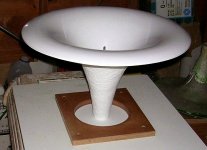
Progress Report from Oz
Here's a picture of the first AH-425 awaiting the cast flange, which will have 7 mounting holes - an inner 3 (3.25" bolt circle diameter) for Altec/GPA 288, 290 and 299 drivers, and an outer 4 (4.0"/102mm bolt circle diameter) for drivers like the Radian 745P, 18Sound 1460A, and BMS 4594ND. (All of these are large-format compression drivers with 1.4" exits.)
Here's a picture of the first AH-425 awaiting the cast flange, which will have 7 mounting holes - an inner 3 (3.25" bolt circle diameter) for Altec/GPA 288, 290 and 299 drivers, and an outer 4 (4.0"/102mm bolt circle diameter) for drivers like the Radian 745P, 18Sound 1460A, and BMS 4594ND. (All of these are large-format compression drivers with 1.4" exits.)
Attachments
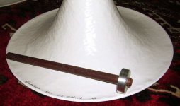
Alignment Tool
I requested that Martin make an "alignment tool", so the centering of the horn on the driver wouldn't be dependent on the precision of the mounting holes on the flange. Here's what he came up with - this allows the driver and horn to be test-fitted to each other (note the flare that matches the throat of the horn and the exit of the compression driver), and when exactly centered, the mounting bolts can be tightened down, and the alignment tool removed.
If the tool gets stuck, the bolts can be loosened, the mounting holes in the cast flange can widened just slightly, and the assembly can be re-mounted again so the alignment tool slides out easily. If the tool is tipped to one side or the other when the bolts are tightened, that tells which mounting holes should be opened up so the compression driver and horn can be exactly centered when the bolts are tightened.
The whole centering process will have to be done a bit gently, since you don't want the hard surface of the tool to deform the softer fiberglass of the horn - I'd rather test-fit the mounting several times to make sure the alignment is exact as possible, then tighten the bolts once it all lines up.
Attachments
Why not just put the horn/driver assembly upside down?
I mean, driver at the bottom, horn mouth face upward. So you may adjust the alignment by just looking at the throat.
It may need 2 persons to get the job done though, if the horn is that large you can not see the throat and reach the mounting screws at the same time...
I mean, driver at the bottom, horn mouth face upward. So you may adjust the alignment by just looking at the throat.
It may need 2 persons to get the job done though, if the horn is that large you can not see the throat and reach the mounting screws at the same time...
One of the criteria that I've focussed on is how an amplifier behaves when exposed to the (highly) resonant back-EMF's of the loudspeaker. These are not merely the big impedance rise at the bottom of the frequency band - but the "buried resonances" that are visible on the waterfall display when a speaker is measured with a FFT or MLS system. These resonant back-EMFs are considerably worse when looking at the currents returned to the amplifier. If the output impedance is constant as waveform swings up and down, the speaker behaves as if it is being driven from a source that has a finite (and small) source resistance. If the output impedance has momentary "kinks" from devices switching on and off through the cycle, the speaker no longer acts as if it is being fed from a virtual resistor, and this interacts with the resonant back-EMFs. Thus, the notorious amp-speaker coloration issues, where speakers sound noticeably different depending on the source amplifier.
I find this subject very interesting. I remember some 4 years ago or more when still in high-school I have stumbled across your site and got lost. I wasn't very acquainted with circuit design and the stuff there blew me out. It also made me very sceptical on all commercial and ..well, "usual" looking circuits.
By the way, regarding out of the box design, have you seen Raals new speaker? Here
Lynn Olson said:
The raw parts cost of the Karna is about $4,000 to $5,000, the electrical design isn't quite finished yet, and it really needs an entirely new mechanical design before it could be put into production. I'm retired, and the prospect of sinking $50,000 to $100,000 into an uncertain venture is not very appealing.
If you go the route of active concepts with five way plus sub as I currently do, you will end up with at least a dozen power amps or so.
Usually its no good idea to use different amp topologies as their sonic patterns hardly ever gel very well. An experienced listener like you always can pin point the break line. Maybe the sub is the only exception to that rule - but I doubt.
This leaves you thinking about overall excellence and economy of amp designs quite some time.
Elias said:Hello,
Interesting is one can actually train himself to hear pinna localisation. I did that and I've regreted that day sinceNow it's very hard to be fooled to hear phantom image!
Instead, I hear three different sources: one is the low freq phantom, two others are the loudspeakers at high freqs. Now how it can be convincing representation of real sound event when the image is split in three?!?
Thanks Elias – pretty much as I feel about.
Depending on mood and intention – and a good soundstage presentation assumed - I can go into the phantom image fully or keep listening on the speakers. So I got off a little bit better .
Sometime I hear razor sharp focused high frequency phantoms at elevated angels far outside the speaker base - up to 180° and more.
This must be a different effect.
Greetings
Michael
Yes the discussion abourt imaging perception has been split of to here:
http://www.diyaudio.com/forums/showthread.php?s=&postid=1596977#post1596977
http://www.diyaudio.com/forums/showthread.php?s=&postid=1596977#post1596977
mige0 said:
If you go the route of active concepts with five way plus sub as I currently do, you will end up with at least a dozen power amps or so.
Usually its no good idea to use different amp topologies as their sonic patterns hardly ever gel very well. An experienced listener like you always can pin point the break line. Maybe the sub is the only exception to that rule - but I doubt.
This leaves you thinking about overall excellence and economy of amp designs quite some time.
Greetings
Michael
Thanks for moving the thread, Variac - much appreciated.
Michael, I doubt I'll be won over by the T and D-amps I've heard so far, and Class AB silicon doesn't really endear me either. Since I really don't want to go over the top on amplifiers, I'm trying to keep complexity of the overall system down - basically, a a fairly classical 2-way with extensions that cover the range below the baffle peak (300 Hz) and above the mass rolloff of the compression driver (3 kHz).
Most of all, I want to avoid digital equalization and time delay, since finding studio-grade DACs and clock-control systems is no small project, and mid-grade DACs can limit the overall resolution of the system.
I'm looking forward to the arrival of the AH-425, and trying out the suggestions that appeared in this thread a few weeks ago about freely suspending the bass drivers so the mechanical reaction forces don't shove the open baffles around. The more I think about it, the more appealing it is - unlike a closed or vented box where even very small leaks grossly alter the LF response, with an open baffle, a "leak" between the freely suspended driver and the enlarged opening of the OB isn't going to change the response much at all.
Going further, hanging the driver from a simple tubular frame has the significant advantage of keeping the emission area of the "enclosure" to an absolute minimum - the smaller the area for a given acceleration, the less the acoustic emission. This minimum-area framework could be one of the unsuspected advantages of an electrostatic loudspeaker - no cabinet coloration because, well, there's no cabinet!
speaking of minimum area frameworks, I am guessing you have seen how the bass is dealt with in the new Raal design coming to RMAF 2008, but in case you haven't:
http://6moons.com/industryfeatures/roadtourserbia/raal.html
http://6moons.com/industryfeatures/roadtourserbia/raal.html
Yes, this is one of the items Alexander shared with me several months ago, during one of our Internet chats with photo-emails to illustrate the conversation. Making the bass sphere out of cast bronze just stunned me - Alexander has a way of doing that, going to the limit of what is physically possible.
Alexander and I were not that impressed with the sound we heard at last year's show - with the exception of the Feastrex and the Audio Kinesis - but I expect his new speaker is going to surprise people. This system has been years in the making - he was talking about a version of it when I first met him - so it'll be interesting to audition it.
There'll probably be some similarity with the overall spatial presentation of the MBL, but with 10~20 dB more dynamic range. Unlike the ultra-low efficiency MBL, it's not going to need a kilowatt amplifier for reasonable dynamics, so that alone will make a big difference. The MBL treble is pretty good, but not in the class of the RAAL ribbon, so I expect a big difference there as well.
Lynn Olson said:
Unlike the ultra-low efficiency MBL, it's not going to need a kilowatt amplifier for reasonable dynamics, so that alone will make a big difference.
Interestingly bass will be driven by dedicated tube amps and user could select amps for mid and highs. For the RMAF and Burning Amp presentations Alex will use tube amps for the top and the bottom. Alex seems extremely pleased with the results, which makes me even more curious to hear it.
- Home
- Loudspeakers
- Multi-Way
- Beyond the Ariel