Re: Some Subjective Measurements
By tilting the baffle back slightly, some significant advantages materialize beyond the time alignment and attendant increase in xover options added: the lobe can be aimed slightly above the head, optimizing reproduction standing or sitting, which are our main modes of listening. Aiming the null towards the floor is the least harmful place, in that floor absorption can be taken to some advantage for the first reflection, and the soft furnishings are more successful at absorbing the nulled response room contribution.
Other benefits of the tilt include reducing the baffle diffraction signature on axis: a target response can be obtained on axis with less colouration of the reverberant sound field, as less jiggery-pokery is needed in the xover to clean up the on axis sound.
Finally, the upward firing tweeter can be easily and passively eq'ed back to target on axis, and resultantly throw more high frequency reverberant energy into the room, better serving the room contribution. Similar advantages exist for the mid/woofer, as the listening position is better optimized for off axis driver radiation. Win-win all around IME. I do this with a design center at about 38 inches off teh ground (my ear is typically 38 to 40").
Lynn Olson said:
Made with the best-quality measuring tape, but unfortunately not traceable to NIST standards.
Sitting on the floor meditation-style (but without the fancy leg moves, which I can't do), my ears are 32.5~33" high, depending on position.
Sitting on different chairs and couches, my ears are 40~49" high, depending on how much I lean back and the recline angle and height of the couch or chair.
Generic 1" dome + 7" midbass speakers (Magico Mini to Cambridge SoundWorks Model Six) typically aim the crossover lobe downward, unless the designer took special steps with the phasing to aim the beam upward (not very common). Since these things usually sit on short stands, I can see why they usually sound better when I sit on the floor, instead of a chair, looking down on them. Pointing them upwards is probably a good idea.
By tilting the baffle back slightly, some significant advantages materialize beyond the time alignment and attendant increase in xover options added: the lobe can be aimed slightly above the head, optimizing reproduction standing or sitting, which are our main modes of listening. Aiming the null towards the floor is the least harmful place, in that floor absorption can be taken to some advantage for the first reflection, and the soft furnishings are more successful at absorbing the nulled response room contribution.
Other benefits of the tilt include reducing the baffle diffraction signature on axis: a target response can be obtained on axis with less colouration of the reverberant sound field, as less jiggery-pokery is needed in the xover to clean up the on axis sound.
Finally, the upward firing tweeter can be easily and passively eq'ed back to target on axis, and resultantly throw more high frequency reverberant energy into the room, better serving the room contribution. Similar advantages exist for the mid/woofer, as the listening position is better optimized for off axis driver radiation. Win-win all around IME. I do this with a design center at about 38 inches off teh ground (my ear is typically 38 to 40").
Lynn Olson said:Well, while we conduct this parallel discussion (which I thoroughly enjoy, by the way) I'd like to bring up the related matter of "out-of-the-room" sound. By this I mean the occasional experience of hearing a vivid impression of a singer being in the house, while you yourself are in different part of the house. The illusion frequently collapses just as you enter the living room, but before you see anything in the room, so I'm not too sure it's a matter of visual perception overriding the sound.
I took some heat for this in another forum, but IME a speaker isn't "right" until it sounds natural in an adjacent room. So many colourations and tonal aberrations that are masked by the near field become laid bare when that masking effect is removed.
Despite having the ability to take accurate quasi anechoic measurements, through NearField+baffle diffraction modeling, spliced to higher frequency quasi anechoic, I still use the "out of room" experience to tune the lower midrange balance (baffle diffraction compensation). It replaces having to take dozens and dozens of off axis measurements (reducing the set to ~ 10 to 20).
Tom Danley said:Lastly, so far as looking at a systems time response in a proportion way, what do you guys think about the Wavelet view? It appears to be something like a CSD but done with a view of acoustic size / wavelength, not time per say.. Seems logical.
I found a nice write-up for those interested.
http://users.rowan.edu/~polikar/WAVELETS/WTpart1.html
Best,
Tom Danley
I'm becoming a big fan of cepstral analysis. Reflections, the ones we can actually deal with such as off adjacent drivers, cabinet edges etc, stick out like a sore thumb, in time. Its like hunting with a high power scope, instead of the opera glasses of CSD.
Time permitting, I'd love to master the art of cepstral measurement editing. I think there's gold in them-thar graphs.
The Cepstral domain analysis looks interesting. While I know some tiny bits about the basics (the spectrum of a spectrum, and its implications) I'd be very interested in more details on this. Can you point me to some, e.g. links? How do I use it in practice (using FFT progs like Spectralab), is there spezialized software around...
- Klaus
- Klaus
Here is some preliminary work I did back in May on cepstral editing in room impulse responses to obtain a speakers anechoic response.
http://www.musicanddesign.com/Cepstral.html
http://www.musicanddesign.com/Cepstral.html
For a teaser:
http://www.libinst.com/cepst.htm
For more meat:
http://ieeexplore.ieee.org/xpl/freeabs_all.jsp?tp=&arnumber=1168523&isnumber=26343
http://www.aes.org/e-lib/browse.cfm?elib=11453
Soundeasy has the capability built into the latest release. This is probably the quickest path short of playing with it yourself.
Raven
Here's the latest thoughts on what I'm planning this fall and winter. It has the most versatility in choosing drivers:
HF: custom RAAL ribbon, standard RAAL ribbon, Stage Accompany planar, matched Heil AMT's, or compression-driver & WG/horn.
8" Widerange: 18Sound 8NMB420, or exotique EnABL'ed Alnico Lowthers, PHL, or Fertin Field-Coil widreange drivers.
12" Midbass: 18Sound 12NDA520 or 12ND710. These drivers are selected for smooth response in the midrange (suitable for professional 2-way applications) and very low distortion in the 100 to 1 kHz region.
15/18" Bass: 18Sound 15NMB420 or 15MB700, RCF L18P300, L18S800 or LF18N802. These are air-movers, true, but large peaks in the midrange are to be avoided. The 18" can replaced with a pair of side-by-side 12" drivers, of the type shown above.
As before, the variable-geometry principle means the the LF drivers are cascaded to aid the widerange driver below the baffle rolloff, so the mids are 8" only, the upper bass is 8+12, and the lower bass is 8+12+18. This avoids the heavy bass-boost equalization of the audiophile-driver OB systems, and retains high headroom thanks to large driver area.
The stereo amplifier used for the MB and Bass drivers allows independent equalization and selection of rolloff frequencies for these drivers - the starting frequency of gradual-slope rolloffs (Bessel recommended) controls the size of the overlap region. This allows control of the response in the 80 to 400 Hz region without using "boost" equalization, keeping amplifier and driver distortion low.
I'll probably use the Behringer DCX equalizer/crossover to get things started, and once I get know the system and room better, maybe switch to a professional analog parametric equalizer like the Rane. As for amplifiers, the Karna all-triode Class A1/A2 amplifier for the widerange and tweeter (with passive crossover), and either good-quality pro amplifier or a pair of Quicksilver PP amplifiers for the Bass/MB drivers (Mike Sanders of Quicksilver lives in Denver now and probably has recommendations for this frequency range).
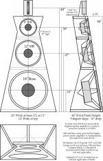
The 9-degree slant gives approximately equal arrival times for the 8 and 18-inch drivers for a listener 5 meters away, as well as aiming the front-panel standing waves and driver peaks upward. The Gary Pimm-style cardioid bass/midbass unit will use the same "Ultratouch" recycled cotton filling as Gary uses, possibly in small pillows between the center strut and the side panels. The addition extension (and quality) of the Pimm bass approach relaxes the subwoofer question quite a bit.
"Raven" feels like the right name - the panels will be gloss or semi-gloss black, and the rear elements will use dark gray felt.
Here's the latest thoughts on what I'm planning this fall and winter. It has the most versatility in choosing drivers:
HF: custom RAAL ribbon, standard RAAL ribbon, Stage Accompany planar, matched Heil AMT's, or compression-driver & WG/horn.
8" Widerange: 18Sound 8NMB420, or exotique EnABL'ed Alnico Lowthers, PHL, or Fertin Field-Coil widreange drivers.
12" Midbass: 18Sound 12NDA520 or 12ND710. These drivers are selected for smooth response in the midrange (suitable for professional 2-way applications) and very low distortion in the 100 to 1 kHz region.
15/18" Bass: 18Sound 15NMB420 or 15MB700, RCF L18P300, L18S800 or LF18N802. These are air-movers, true, but large peaks in the midrange are to be avoided. The 18" can replaced with a pair of side-by-side 12" drivers, of the type shown above.
As before, the variable-geometry principle means the the LF drivers are cascaded to aid the widerange driver below the baffle rolloff, so the mids are 8" only, the upper bass is 8+12, and the lower bass is 8+12+18. This avoids the heavy bass-boost equalization of the audiophile-driver OB systems, and retains high headroom thanks to large driver area.
The stereo amplifier used for the MB and Bass drivers allows independent equalization and selection of rolloff frequencies for these drivers - the starting frequency of gradual-slope rolloffs (Bessel recommended) controls the size of the overlap region. This allows control of the response in the 80 to 400 Hz region without using "boost" equalization, keeping amplifier and driver distortion low.
I'll probably use the Behringer DCX equalizer/crossover to get things started, and once I get know the system and room better, maybe switch to a professional analog parametric equalizer like the Rane. As for amplifiers, the Karna all-triode Class A1/A2 amplifier for the widerange and tweeter (with passive crossover), and either good-quality pro amplifier or a pair of Quicksilver PP amplifiers for the Bass/MB drivers (Mike Sanders of Quicksilver lives in Denver now and probably has recommendations for this frequency range).
The 9-degree slant gives approximately equal arrival times for the 8 and 18-inch drivers for a listener 5 meters away, as well as aiming the front-panel standing waves and driver peaks upward. The Gary Pimm-style cardioid bass/midbass unit will use the same "Ultratouch" recycled cotton filling as Gary uses, possibly in small pillows between the center strut and the side panels. The addition extension (and quality) of the Pimm bass approach relaxes the subwoofer question quite a bit.
"Raven" feels like the right name - the panels will be gloss or semi-gloss black, and the rear elements will use dark gray felt.
Attachments
KSTR said:The Cepstral domain analysis looks interesting. While I know some tiny bits about the basics (the spectrum of a spectrum, and its implications) I'd be very interested in more details on this. Can you point me to some, e.g. links? How do I use it in practice (using FFT progs like Spectralab), is there spezialized software around...
- Klaus
Please realize that the Cepstrum is obtained as an FFT of the Spectrum. But since the FFT is a completely reversible linear process and the Inverse FFT of the Spectrum is the impulse response, the ceptrum of a system response is thus the same thing as its impulse response, except for the scaling. Ceptrums make sense when dealing with blind measures of noise etc. where one can glean information about the number of independent noise sources or the number of paths, etc. but for a system where you have an input and an output, the Cepstrum response and the Impulse response are the same thing.
gedlee said:
Please realize that the Cepstrum is obtained as an FFT of the Spectrum. But since the FFT is a completely reversible linear process and the Inverse FFT of the Spectrum is the impulse response, the ceptrum of a system response is thus the same thing as its impulse response, except for the scaling. Ceptrums make sense when dealing with blind measures of noise etc. where one can glean information about the number of independent noise sources or the number of paths, etc. but for a system where you have an input and an output, the Cepstrum response and the Impulse response are the same thing.
I agree Earl. The idea of using cepstral editing for recovery of low frequency information came form some earlier work on the subject that Bohdan (Sound Easy developer) came across (or was requested to look at). The supposed reason to use the real cepstrum was that it would make reflection more apparent, thus easier to edit out. Frankly, I didn't buy it because I felt, and demonstrated, that I could do just as well by editing the impulse response.
The best results using cepstral editing, as shown on the web page I posted, are obtained when the cepstrum is tailed in a manner consistent with the low frequency cut off of the speaker system. That is just as easy to do for the impulse response as it is for the cepstrum and really more akin to modeling the low frequency response than recovering it from a noisy impulse. I feel the near filed/far filed merge with modeled baffle step correction is easier and close to the truth since only the baffle step is modeled.
Lynn Olson said:
Hmm, I'd like to take you up on that. I don't know anyone in Italy, and unfortunately, I haven't gotten any phone call or or e-mail responses from a US importer, Loudspeakers Plus. More than a week has gone by - either they're on vacation or ... ?
I'd particularly like the know the suitability for the highest-quality midbass application of the 12ND710, the 12NDA520, or the 8NMB420. Smooth time-decay characteristics in the 1~5 kHz range and low IM distortion in the 200 Hz ~2 kHz range are a priority.
I'm also curious which of the 15" drivers would have the lowest distortion in the 80~400 Hz region while avoiding severe resonances in 1~3 kHz region. Lots of questions here, and not all the answers are on the 18Sound website.
Lynn
Mr. Previ answered. He will contact you.
")
Re: Raven
Hi Lynn, it looks nice with well staggered radiating dimensions. That 9 deg slant maybe a bit over the top. You don't need to get the voice coils inline. The radiation centres must be aligned by experiment and they will appear further front IMHO. My rough guess is that maybe you are going to need 5 deg slant.
Lynn Olson said:
The 9-degree slant gives approximately equal arrival times for the 8 and 18-inch drivers for a listener 5 meters away, as well as aiming the front-panel standing waves and driver peaks upward. y felt.
Hi Lynn, it looks nice with well staggered radiating dimensions. That 9 deg slant maybe a bit over the top. You don't need to get the voice coils inline. The radiation centres must be aligned by experiment and they will appear further front IMHO. My rough guess is that maybe you are going to need 5 deg slant.
john k... said:
I agree Earl. The idea of using cepstral editing for recovery of low frequency information came form some earlier work on the subject that Bohdan (Sound Easy developer) came across (or was requested to look at). The supposed reason to use the real cepstrum was that it would make reflection more apparent, thus easier to edit out. Frankly, I didn't buy it because I felt, and demonstrated, that I could do just as well by editing the impulse response.
The best results using cepstral editing, as shown on the web page I posted, are obtained when the cepstrum is tailed in a manner consistent with the low frequency cut off of the speaker system. That is just as easy to do for the impulse response as it is for the cepstrum and really more akin to modeling the low frequency response than recovering it from a noisy impulse. I feel the near filed/far filed merge with modeled baffle step correction is easier and close to the truth since only the baffle step is modeled.
John,
While near/far field splices will provide you the full bandwidth, it unfortunately does not provide any improvements in inherent frequency resolution.
The ability to see narrowband driver or cabinet resonances will be no more enhanced than in the original, coarse, quasi anechoic measure. By removing the offending echo, we have the opportunity to improve frequency resolution, by allowing larger FFT windows.
This is all about signal processing, not having the card capture new physical data. While there is no new information being processed, by viewing it in a different manner, it can be more effectively interpreted and new aspects of teh existing information revealed.
I'm very optimistic the cepstral view can be used to provide much better edits than impulse response measures. This optimism is based on seeing the significant improvements we made with echo cancellation algorithms in the 90s, all through changes in how existing data was viewed and processed (RLS/MLS changes, onset detection, noise detection, frequency binning etc). The echo cancellation problem has very strong parallels to this problem.
Perhaps the cepstral edit can be used for system identification of resonances and fine grain frequency behaviour, whereas the existing, smoothed, quasi anerchoic/nf splice method can be used for a smoothed frequency response view.
Its still early days for cepstral analysis, of loudspeakers.
"'m very optimistic the cepstral view can be used to provide much better edits than impulse response measures. "
I wouldn't make a bet on that if I were you. This is old old territory and what you are suggesting does work any better, maybe even worse, than using the impulse response. I wrote a paper on this over 15 years ago.
I wouldn't make a bet on that if I were you. This is old old territory and what you are suggesting does work any better, maybe even worse, than using the impulse response. I wrote a paper on this over 15 years ago.
gedlee said:"'m very optimistic the cepstral view can be used to provide much better edits than impulse response measures. "
I wouldn't make a bet on that if I were you. This is old old territory and what you are suggesting does work any better, maybe even worse, than using the impulse response. I wrote a paper on this over 15 years ago.
I'd unhesitantly put money on it, but what I need is time.
I heard the exact same lamenting when we revolutionized the verification of echo cancellers in the 90s, and this problem isn't so different.
A 15 year old paper doesn't change that.
I'd prefer to work out some proposals with my old ecan colleague. One already sees the light and has that old glimmer.
No disrespect, but this was my field of expertise.
Raven
Very much look forward to contacting Mr. Previ of 18Sound - many questions about the most suitable drivers.
Hi Salas, I did a little simple geometric modelling and found that for a 5-meter listening distance, there's a 4-inch (100mm) offset between the 8 and 18-inch driver. (Listening at the same 39-inch height as the 8-inch driver.) Add an inch for the deeper cone of the larger driver, and that's 5 inches, which translates into a 9-degree slant.
If you listen at higher than 39 inches, or closer than 5 meters, you need more slant. The only zero-slant condition is listening at 24.5 inches off the floor, the centerline between the 8 and 18-inch drivers.
This is assuming all drivers have equivalent acoustic lowpass functions. In practice we have acoustic lowpass filtering like this:
Lowpass for 8-inch: 2nd-order at 2~2.5 kHz
Lowpass for 12-inch: 1st-order or Bessel 2nd-order at 200~300 Hz (additional filtering above 1 kHz to force to idealized rolloff)
Lowpass for 15/18-inch: 1st-order or Bessel 2nd-order at 80~120 Hz (additional filtering above 1 kHz to force idealized rolloff)
The larger drivers have summed electrical + acoustic lowpasses that moves them further back in space (relative to the widerange driver). This would imply that I need more offset if I want the arrival times to be the same.
What's your take on this? If you assume a 5-degree slant, with identical drivers, fed the same frequency response - looking at geometry alone, it looks to me like the sound from driver closest to the floor arrives first.
P.S. Since we are free to use Nth-order Bessel lowpass filters for the MB and Bass drivers, I'm aware they can be moved back in space relative to the widerange driver by simply increasing the order of the non-overshooting Bessel filter. But this is a one-way street: they can't be moved acoustically forward of the WR driver unless the whole system uses a digital delay system, something I'd like to avoid as a design requirement.
thomaseliot said:
Lynn
Mr. Previ answered. He will contact you.
Very much look forward to contacting Mr. Previ of 18Sound - many questions about the most suitable drivers.
salas said:
Hi Lynn, it looks nice with well staggered radiating dimensions. That 9 deg slant maybe a bit over the top. You don't need to get the voice coils inline. The radiation centres must be aligned by experiment and they will appear further front IMHO. My rough guess is that maybe you are going to need 5 deg slant.
Hi Salas, I did a little simple geometric modelling and found that for a 5-meter listening distance, there's a 4-inch (100mm) offset between the 8 and 18-inch driver. (Listening at the same 39-inch height as the 8-inch driver.) Add an inch for the deeper cone of the larger driver, and that's 5 inches, which translates into a 9-degree slant.
If you listen at higher than 39 inches, or closer than 5 meters, you need more slant. The only zero-slant condition is listening at 24.5 inches off the floor, the centerline between the 8 and 18-inch drivers.
This is assuming all drivers have equivalent acoustic lowpass functions. In practice we have acoustic lowpass filtering like this:
Lowpass for 8-inch: 2nd-order at 2~2.5 kHz
Lowpass for 12-inch: 1st-order or Bessel 2nd-order at 200~300 Hz (additional filtering above 1 kHz to force to idealized rolloff)
Lowpass for 15/18-inch: 1st-order or Bessel 2nd-order at 80~120 Hz (additional filtering above 1 kHz to force idealized rolloff)
The larger drivers have summed electrical + acoustic lowpasses that moves them further back in space (relative to the widerange driver). This would imply that I need more offset if I want the arrival times to be the same.
What's your take on this? If you assume a 5-degree slant, with identical drivers, fed the same frequency response - looking at geometry alone, it looks to me like the sound from driver closest to the floor arrives first.
P.S. Since we are free to use Nth-order Bessel lowpass filters for the MB and Bass drivers, I'm aware they can be moved back in space relative to the widerange driver by simply increasing the order of the non-overshooting Bessel filter. But this is a one-way street: they can't be moved acoustically forward of the WR driver unless the whole system uses a digital delay system, something I'd like to avoid as a design requirement.

Ravens have also been attributed to carrying souls from this world to the next, so perhaps in this case it (Raven speaker) can carry the soul of the performance from the original world to his.pdan said:The raven is a symbol of death in old paintings
I like the look of the Raven. Nice sketch.
Not such a huge speaker after all. I've had OBs about that big in my small living room. The taper and final pinch at the top give it an elegant feel. There sure is a lot of cone surface and magnet weight going on.
When you say "In practice we have acoustic lowpass filtering like this:" do you mean these are your target acoustic curves and you will make whatever electrical filters are needed to achieve it? Or are you talking just electrical?
That's very nice, Brett.
Nice sketch.Not such a huge speaker after all. I've had OBs about that big in my small living room. The taper and final pinch at the top give it an elegant feel. There sure is a lot of cone surface and magnet weight going on.
When you say "In practice we have acoustic lowpass filtering like this:" do you mean these are your target acoustic curves and you will make whatever electrical filters are needed to achieve it? Or are you talking just electrical?
(Raven speaker) can carry the soul of the performance from the original world to his.
That's very nice, Brett.
- Home
- Loudspeakers
- Multi-Way
- Beyond the Ariel