Sorry if I seamed to be obsessive about this . So far my testing with an impedance meter has yielded result much like yours ( need to be in a range for it to work well). My question was based on design philosophy and reasoning rather than a faster thumb nail approach . Not meaning to over think it as it where . Nor be obsessive about this. Over time on this site I have seen the rule of thumb range view be stomped to death by the exact math freaks only to then give a range of proper values that fall close to that rule of thumb starting point . Hope I have not come off pedantic on this that was not my intent.I have found that once you get in the right neighborhood for R with QUASIMODO there is a range where the waveform changes so little over a surprising variety of R values that one can get really picky if you want but, in my LIMITED experience, all you have to do is get close to get rid of the ringing.
Not as if you will need 0.1% resistors!
My first tested transformer (for the mono J2 project) you can go between 20R and 38R with the slightest difference for the first peak.
I get the feeling there is no reason to obsess over the EXACT value of R but every reason to incorporate the snubber.
I am thinking it is better to go high than low on the value of R. I would worry one can go too low and likely lose some life in the sound of your amplifier. But you cannot beat QUASIMODO for telling you where the neighborhood is. You can pick the house you want once you get there.

You made a fine point with a range of +/- 31% from center on you test 1% are not need.Triodethom,
My comments were not aimed at you. I was making a general post of what I had found!
And to think I thought I was the ONLY audio kook in Georgia! I am in Duluth.

![IMG_1836[1].jpg](https://www.diyaudio.com/community/data/attachments/544/544075-d7ebc7444b3e27b27cf2a5be57f04818.jpg "IMG_1836[1].jpg")
Nice looking. I do like the copper bus bars. I have 2 sets of those for my DIY VFet build. I need to do the power supplies, when life allows.
Well done, and thanks for the picture.
Decided to post this here.
Today mounted up some HFA50PA60CPbF diodes onto a PCB.
The plan is not to repeat the excellent work of Mark but to see if simply replacing standard block bridge rectifiers to Hexfred diodes provides a measureable improvement, when used within the context of a diy class A amplifier. Each channel of the amplifier is biased at 1.5A.
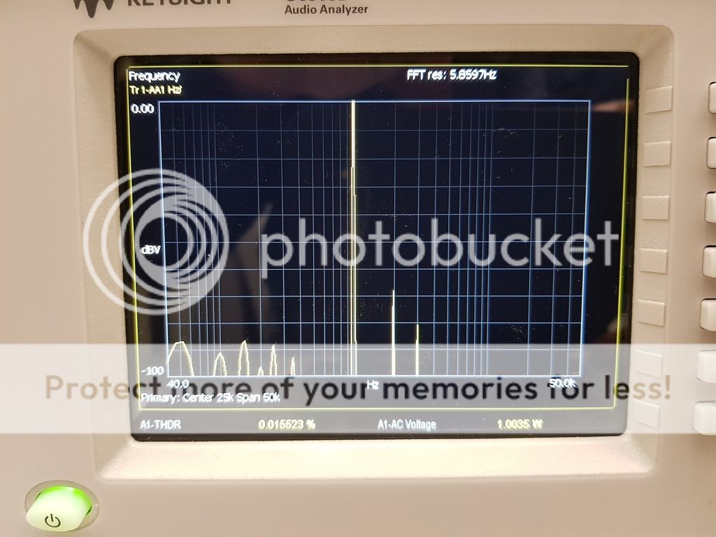
Here is the result with the standard bridge rectifiers, you can see the rectified noise is filled with harmonics up to 350Hz.
Today mounted up some HFA50PA60CPbF diodes onto a PCB.
The plan is not to repeat the excellent work of Mark but to see if simply replacing standard block bridge rectifiers to Hexfred diodes provides a measureable improvement, when used within the context of a diy class A amplifier. Each channel of the amplifier is biased at 1.5A.
Here is the result with the standard bridge rectifiers, you can see the rectified noise is filled with harmonics up to 350Hz.
Last edited:
The scope of this thread has now far exceeded the content of the original post, it might make more sense at this point in time to rename this thread to, Better Rectifier Diodes For Class A Amps.
Here is the result with the standard bridge rectifiers, you can see the rectified noise is filled with harmonics up to 350Hz.
Compare "350 Hz" against the natural oscillation frequency of your un-snubbed transformer secondary. Based on the uploaded measurement data from hundreds of diyAudio members, I predict you'll find there is a wide gap between the two.
let f1 = 350 Hz
let f2 = the natural oscillation frequency of your un-snubbed transformer secondary
let g = (f2 - f1)
g is an abbreviation of gap
What is the numerical value of g, in Hertz? Would you say g is a big number? If so, would you say the gap is a big number? If so, would you say the gap is wide?
let f2 = the natural oscillation frequency of your un-snubbed transformer secondary
let g = (f2 - f1)
g is an abbreviation of gap
What is the numerical value of g, in Hertz? Would you say g is a big number? If so, would you say the gap is a big number? If so, would you say the gap is wide?
Decided to post this here.
Today mounted up some HFA50PA60CPbF diodes onto a PCB.
The plan is not to repeat the excellent work of Mark but to see if simply replacing standard block bridge rectifiers to Hexfred diodes provides a measureable improvement, when used within the context of a diy class A amplifier. Each channel of the amplifier is biased at 1.5A.
Here is the result with the standard bridge rectifiers, you can see the rectified noise is filled with harmonics up to 350Hz.
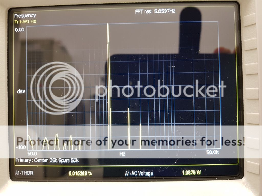
With the Hexfreds installed.
No measurable improvement. If anything slightly worse. Hahaha

With analog osciloscope I must to turn off light in room to see that shadow spike. With digital osciloscope I dont have experience.
Then I sniffing on the rails and on the amplifier output without input signal.
With Mhz bandwith amplifier its funny.
I using this vilager method, then I playing, until I kill that spike.
Then I sniffing on the rails and on the amplifier output without input signal.
With Mhz bandwith amplifier its funny.
I using this vilager method, then I playing, until I kill that spike.
Attachments
- Status
- This old topic is closed. If you want to reopen this topic, contact a moderator using the "Report Post" button.
- Home
- Amplifiers
- Pass Labs
- Better rectifier for the SIT 1