I have a CDP with dual opamps for output buffers and I want to use two single DIP opamps with a single to dual Brown Dog Adapter for each channel. I need to raise the Brown Dog Adapters above the capacitors next to the buffer opamps. I could stack sockets but I'm trying to think of a better approach. Any ideas?
seoman said:Put the adaptor on the other side.
Desolder the pins and let them stick out on the components side. (of the adaptor)
Now you can put the adaptor real close to the pcb
at the bottomside of the pcb
Just a thought
zanash said:that wont work the chip socket will be in the mirror image position.
Read the suggestion carefully. It will work !
i'd probably extend the pins on the adaptor and solder it straight to the board? probably useing those stirps of metal pins you can get with the plastic insulator half way down.. sometimes used on stuff to raise daughterboards of the main pcb so it will clear components underneath.. I have some in my parts bin that have pins the right size to fit perfectly in an IC socket aswell.. but personally i would solder it to the adaptor and to the CDP's board... Mabey something liek this would work for you?
Owen
Owen

Re: raising the adapter
You naughty boy...
You'll have a much longer feedback loop (= bad) and PSU bypass caps a mile away (= bad).
Sometimes I wonder why do people go to so much trouble.
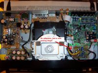
Just forget the original circuit, sometimes it's easier to make a small board from scratch and fit two single opamps there, decent caps... all you need is to cut some PCB tracks and V+, V- and ground to that board.
This one goes even further, with dedicated PSU.
Elso Kwak said:
You naughty boy...
You'll have a much longer feedback loop (= bad) and PSU bypass caps a mile away (= bad).
Sometimes I wonder why do people go to so much trouble.
Just forget the original circuit, sometimes it's easier to make a small board from scratch and fit two single opamps there, decent caps... all you need is to cut some PCB tracks and V+, V- and ground to that board.
This one goes even further, with dedicated PSU.
Attachments
Re: Re: raising the adapter
Nevertheless it works as I xplained you over there too!!
Me naughty? What do you know!
carlosfm said:You naughty boy...
You'll have a much longer feedback loop (= bad) and PSU bypass caps a mile away (= bad).
Sometimes I wonder why do people go to so much trouble.
Just forget the original circuit, sometimes it's easier to make a small board from scratch and fit two single opamps there, decent caps... all you need is to cut some PCB tracks and V+, V- and ground to that board.
This one goes even further, with dedicated PSU.
Nevertheless it works as I xplained you over there too!!
Me naughty? What do you know!
Re: Re: Re: raising the adapter
Yes, it "just" works.

Elso Kwak said:Nevertheless it works as I xplained you over there too!!
Yes, it "just" works.
Elso Kwak said:Me naughty? What do you know!
Re: Re: Re: Re: raising the adapter
No it works perfectly!!!!!!!!
Such good sound from OPA627BP as IV-converter
carlosfm said:Yes, it "just" works.
No it works perfectly!!!!!!!!
Such good sound from OPA627BP as IV-converter
Re: Re: Re: Re: Re: raising the adapter
Elso, I know what you mean, the OPA627BP works very well as I/V but IME it is very sensitive to the PSU layout.
You'll have even better performance with good PSU bypass.
It is audible, oh yes.
Elso Kwak said:No it works perfectly!!!!!!!!
Such good sound from OPA627BP as IV-converter
Elso, I know what you mean, the OPA627BP works very well as I/V but IME it is very sensitive to the PSU layout.
You'll have even better performance with good PSU bypass.
It is audible, oh yes.
Re: Re: Re: Re: Re: Re: raising the adapter
you know more than me.....oh no.......


carlosfm said:Elso, I know what you mean, the OPA627BP works very well as I/V but IME it is very sensitive to the PSU layout.
You'll have even better performance with good PSU bypass.
It is audible, oh yes.
you know more than me.....oh no.......
Re: Re: Re: Re: Re: Re: Re: raising the adapter
Elso, do you read the datasheets? Actually most talk about having caps ON the chip's pins.
Well, these days op-amps are getting so fast that even the (old) standard pinout (pins 4 and 7/8) is totally unapropriate.
What is it that you find so fine in using adaptors?
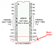
When they don't have to respect a standard pinout, they do it much better.
Look:
Elso Kwak said:you know more than me.....oh no.......
Elso, do you read the datasheets? Actually most talk about having caps ON the chip's pins.
Well, these days op-amps are getting so fast that even the (old) standard pinout (pins 4 and 7/8) is totally unapropriate.
What is it that you find so fine in using adaptors?
When they don't have to respect a standard pinout, they do it much better.
Look:
Attachments
Re: Re: Re: Re: Re: Re: Re: Re: raising the adapter
I read datasheets, Application Notes, Design Notes etc. Carlosfm. I have a huge collection.
The OPA627 is not a crazy fast opamp. Actually I don't like these new hyper-fast opamps for audio you are referring to.
The adapter with two OPA627 works very well in my own KWAK-DAC and in the Sony SCD-1 SACD player. I placed decoupling caps caps at the supply pins of the original supply pins in the Sony though. Also tried OP275 there. Originally the Sony had OPA2604s.
So you see I am not talking theoretical limbo-jumbo. Also don't forget the band-with of the opamp is drastically reduced by the cap across the feedback resistor: 3n3F in my DAC ; 4n7F in the Sony.
The adapters are fine as I can use the OPA627 in the Sony and existing DAC without modding too much and yet enjoying the sound.
carlosfm said:
Elso, do you read the datasheets? Actually most talk about having caps ON the chip's pins.
Well, these days op-amps are getting so fast that even the (old) standard pinout (pins 4 and 7/8) is totally unapropriate.
What is it that you find so fine in using adaptors?
When they don't have to respect a standard pinout, they do it much better.
Look:
I read datasheets, Application Notes, Design Notes etc. Carlosfm. I have a huge collection.
The OPA627 is not a crazy fast opamp. Actually I don't like these new hyper-fast opamps for audio you are referring to.
The adapter with two OPA627 works very well in my own KWAK-DAC and in the Sony SCD-1 SACD player. I placed decoupling caps caps at the supply pins of the original supply pins in the Sony though. Also tried OP275 there. Originally the Sony had OPA2604s.
So you see I am not talking theoretical limbo-jumbo. Also don't forget the band-with of the opamp is drastically reduced by the cap across the feedback resistor: 3n3F in my DAC ; 4n7F in the Sony.
The adapters are fine as I can use the OPA627 in the Sony and existing DAC without modding too much and yet enjoying the sound.
Elso, look at the title of the thread.
I just tried to answer the question, don't you agree that it's better to avoid adaptors?
From time to time I have to scavenge this:
OPA627 datasheet, page 9:
"Power supply connections should be bypassed with good high frequency capacitors positioned close to the op amp pins. In most cases 0.1µF ceramic capacitors are adequate.
The OPA627/637 is capable of high output current (in excess of 45mA). Applications with low impedance loads or capacitive loads with fast transient signals demand large currents from the power supplies. Larger bypass capacitors such as 1µF solid tantalum capacitors may improve dynamic performance in these applications."
IME for audio use, 1uF close to the pins is still too small.
Here's something a little better written:
AD815 datasheet, Rev. B, page 10:
"Adequate power supply bypassing can be critical when optimizing the performance of a high frequency circuit.
Inductance in the power supply leads can form resonant circuits that produce peaking in the amplifier’s response.
In addition, if large current transients must be delivered to the load, then bypass capacitors
(typically greater than 1 µF) will be required to provide the best settling time and lowest distortion.
A parallel combination of 10.0 µF and 0.1 µF is recommended. Under some low frequency applications, a bypass capacitance of greater than 10µF may be necessary."
The last sentence, that I put in bold, indicates what you should do when using the chip for audio applications.
I don't agree with some datasheets that say you must only use small ceramic bypasses on the chip's pins and larger caps can be several cm away, but then again we must have in mind that most opamps were not made for audio use, and the datasheets just reflect that.
But these two examples are not so bad.
You know, bass suffers when the caps are far, and the OPA627 doesn't like that at all! And then they say it has untight bass...
- Status
- This old topic is closed. If you want to reopen this topic, contact a moderator using the "Report Post" button.
- Home
- Source & Line
- Digital Source
- Better Options than Stacking Sockets?