Hello folks,
I have a Headway EDB2 HE instrument/mic preamp box that provides 11 volts of bias voltage on the tip of one of its jack input sockets.
I am looking to use it to power a DPA 4061 microphone that I have read should be fed with no more than 9 volts of bias voltage with 5v being the minimum to operate.
The DPA 4061 will be mounted in a guitar and wired to the endpin jack.
I am hoping that I can step down the 11volt from my preamp to a safe level for the mic by using one or two small parts that I might be able to solder into the jack on the end of the lead that will go into the Headway unit.
The DPA4061 current consumption is stated as "Typ. 1.5 mA".
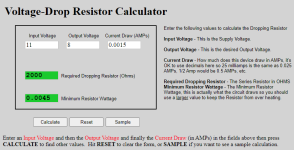
Using an online calculator, it looks like I can use a 2k resistor in series from the 11 volt and this will give 8 volts bias voltage to the DPA4061.
Are there any reasons why this might not be the best approach? I note that of course that if the current consumption of the mic changes the voltage drop will change.
I am unsure how much deviation there is on the current draw of a mic such as this?
The mic will be biased on the same conductor that will also be used for the signal, a small drop in signal should not b a problem but again are there any other considerations i should be making here?
Should I be using a voltage divider instead or is there another simple and better route?
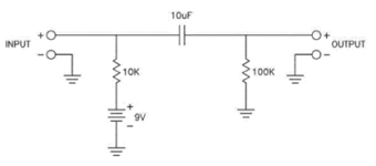
I did find a schematic on a forum (see attached) for using a 9 volt battery source with a DPA 4061 and this appears to use a 10K resistor which I assume drops the voltage of the 9 volt battery. This suggests that my calculation above where I have arrived at a 2k resistor from an 11v source must be wrong.
Any guidance here would be very gratefully received!
Many thanks in advance.
I have a Headway EDB2 HE instrument/mic preamp box that provides 11 volts of bias voltage on the tip of one of its jack input sockets.
I am looking to use it to power a DPA 4061 microphone that I have read should be fed with no more than 9 volts of bias voltage with 5v being the minimum to operate.
The DPA 4061 will be mounted in a guitar and wired to the endpin jack.
I am hoping that I can step down the 11volt from my preamp to a safe level for the mic by using one or two small parts that I might be able to solder into the jack on the end of the lead that will go into the Headway unit.
The DPA4061 current consumption is stated as "Typ. 1.5 mA".
Using an online calculator, it looks like I can use a 2k resistor in series from the 11 volt and this will give 8 volts bias voltage to the DPA4061.
Are there any reasons why this might not be the best approach? I note that of course that if the current consumption of the mic changes the voltage drop will change.
I am unsure how much deviation there is on the current draw of a mic such as this?
The mic will be biased on the same conductor that will also be used for the signal, a small drop in signal should not b a problem but again are there any other considerations i should be making here?
Should I be using a voltage divider instead or is there another simple and better route?
I did find a schematic on a forum (see attached) for using a 9 volt battery source with a DPA 4061 and this appears to use a 10K resistor which I assume drops the voltage of the 9 volt battery. This suggests that my calculation above where I have arrived at a 2k resistor from an 11v source must be wrong.
Any guidance here would be very gratefully received!
Many thanks in advance.
Attachments

The schematic with the 10k resistor doesn't make sense for 1.5mA current draw, so you're correct that something doesn't add up there.
I don't know this mic, but using a voltage divider is a lower-risk approach. If it truly can't handle more than 9V, it's not necessarily safe to feed it 11V through a resistor and count on its current draw to drop the voltage. While current is beginning to flow, it could briefly be exposed to 11V, and there's no guarantee it can handle that. (Probably it will be fine, if you don't mind risking the mic to find out.) To be safe, we need <9V before the mic is connected, so voltage divider it is.
The right ratio is 3:8 to get 8V from 11V. The voltage divider needs to be capable of supplying 1.5mA at >5V, which means the upper resistor probably needs to be smaller than 3.3k. Don't want to go too low or the voltage divider will sink too much current all by itself. I'd start with an 820R:2.2k voltage divider. Check voltage before and after connecting the mic to get a better picture of what's happening.
Thanks so much for your reply. Yes I think the current draw spec is perhaps a maximum.
Yes I was wondering about a voltage divider instead. I found a forum member who had measured the DC resistance of the mic (mine hasn't arrived yet) and it is 30K. Perhaps I can use a dummy resistor to represent the mic load though I guess in practise the actual mic load will behave differently.
I did just find the following information on another forum where the members were discussing the correct series resistor to be used with a 9 volt battery and the DPA 4061. I think it is to safe guard against a fresh battery that will exceed 9 volts when new. The first text is an email from DPA the second I think is an email from a third party manufacturer of battery power packs for mics.
The formula given seems to suggest that the current draw is 0.7mA.
I am unsure what the -2.5 in the formula represents, is this just the voltage drop to bring the 9 volt battery down by 2.5 volts ?
Therefore a fresh battery would be 9.5v - 2.5v = 7 / 0.0007 = 10,000 ohm resistor which is what is used in the 9 volt battery 4061 bias schematic i posted earlier.
Would I therefore be safe applying this formula to my 11 volt supply and how do I apply the same formula?
------------------------------
The formula for calculating the appropriate series
resistor is: R = ((Vs - 2.5)V/0.7mA).
4061 powered by a 9v battery will require a series resistor in the 6K8 - 9K1
range.
Please call if you have any other questions.
Best Regards,
DPA Microphones, Inc.
-----------------------------
and Len uses 13K with his HEB/4061 and said:
We have a slightly different one from a few years ago. We can confirm the value we use from experience.
The formula you sent would specify a 10K Ohm resistor for use with a fresh 9.5 V battery. We know from experience that the 4060-series has problems with a 10K.
so i guess it comes down to how hot are your fresh 9V batteries? i think 10-13K would be a safer bet if you dont wanna cook your microphones
---------------------------------
Thank you for your reply. Yes it was suggested to me elsewhere to use diodes to drop the voltage but the mic signal would also have to pass through those diodes as the bias voltage is being provided on the tip of the preamp jack input where the mic signal goes.
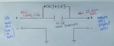
I have attached a schematic for one suggestion I have received, although in this case, it seems that half of the ac waveform from the mic signal will pass through the diodes and join the full wave mic signal that will pass through the 10uf cap (cap blocks the bias voltage). I am unsure if this will negatively affect the mic signal to the preamp.
I have attached a schematic for one suggestion I have received, although in this case, it seems that half of the ac waveform from the mic signal will pass through the diodes and join the full wave mic signal that will pass through the 10uf cap (cap blocks the bias voltage). I am unsure if this will negatively affect the mic signal to the preamp.
Attachments
My idea will not work, as I wasn't aware that the mic signal has to go over the same wire. So an ohmic divider as supposed by @sahazel will be the solution. Btw, in the layouts I found in the internet, many of them have a resistor followed by a capacitor in the feeding line going to the two divider resistors. The resistor limits current flow, the capacitor stabilizes and filters the DC voltage.
An example of this:
http://www.victoriana.com/phantomspeisung-mikrofon-schaltung-k.html
An example of this:
http://www.victoriana.com/phantomspeisung-mikrofon-schaltung-k.html
- Home
- Live Sound
- Instruments and Amps
- Best way to step down 11v bias voltage to below 9v for a DPA 4061 microphone