Hi there,
This is the first time I have posted on here and the reason is because there seems to be alot off talk regarding tapped horn subs. I currently have two FI Q18" drivers (pre 2010 model) which are currently in 2 15 cu ft boxes with multi tune on them. 12.5hz, 17.5hz and 21.5hz. I am running an EP4000 2 ohms stereo to both subs as they are dual 1 ohm drivers.
Is it possible to put those drivers into a tapped horn? Everything I have read so far has pretty much baffled me so I am wondering is there a better way to learn how to use this program and understand the termonology off each word etc...
I wanted to do something different basically as I have done a sealed and ported sub but would be interested if I can actually get more output and less distortion buy running two tapped horns instead.
I would appreciate any advice you all can give me.
cheers
Graham
Ok, I spent about 4 hours last night swatting up on hornresp and understood some bits but not many. I tried my Q18 driver and the box came out at 1300 litres which is huge but then found out that I didn't have it set to tapped horn. Learning process I guess.
One thing that is baffling me is how to work out the S1 - S4 input values. I then tried it on a TC sounds Epic 12" driver x2 but couldn't get a very good response and then found myself changing the input values to all sorts off values to see how it affected the response but then just got myself deeper and deeper.
I have tried reading about 4 different tutorials but they all explain things in different ways.
Can someone explain to me in simple terms how to calculate the S values along with the con values too.
cheers
Graham
the s vallues are the service area at one point in the horn.
the l vallue is the lengt from one section(s1) to the next section(s2)

i suggest to read the help file in the program .
its usefull to use the loudspeaker wizzard.
note ,you need 2 sections be4 you can use the wizzard.
the l vallue is the lengt from one section(s1) to the next section(s2)
i suggest to read the help file in the program .
its usefull to use the loudspeaker wizzard.
note ,you need 2 sections be4 you can use the wizzard.
lilmike has a nice tutorial thread going:
Simple Tapped Horn Tutorial using Hornresp - AVS Forum
Then work yourself through some examples, e.g.:
Reed Exodus Anarchy 25hz Tapped Horn - AVS Forum
,or
http://www.diyaudio.com/forums/subw...ped-horn-th-spud.html?perpage=25&pagenumber=1
Regards,
Simple Tapped Horn Tutorial using Hornresp - AVS Forum
Then work yourself through some examples, e.g.:
Reed Exodus Anarchy 25hz Tapped Horn - AVS Forum
,or
http://www.diyaudio.com/forums/subw...ped-horn-th-spud.html?perpage=25&pagenumber=1
Regards,
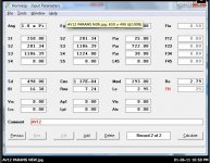
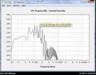
Thanks guys, I played with hornresp last night with the help from a guy on avsforum and managed to model a 15hz horn with 2 AV12 drivers. Box came out at 560 litres and 125db at 16hz.
The thing I am not sure about is when it comes to doing a drawing how do you know what the dimensions are off the square areas are from the throat to the mouth. I would like to make the horn in two folds so it is taller rather than square but am not sure how to do this.
I have read lots off tutorials but none actually mention how to do this.
I understand that the S values are volumes (I think) but how do you work the dimensions off those areas.
cheers
Graham
Hi Oliver,
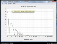
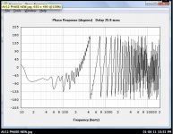
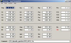
Here are some grabs off what I modelled for the dual AV12 horn. I wanted it to go down to 15hz and came out to 560litres.
Perhaps you could have a look and let me know it looks and what can be modified to make it better.
I have 250 for my S1 value and the length is 25 so what would the throat size be. Sorry if I sound vague, I am a pure beginner.
cheers
Graham
Attachments
Suggestions only.
Hi Graham,
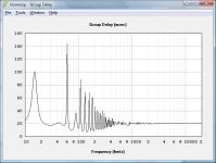
Getting to 15Hz results in a very long horn with all the associated delay problems.
In general I like to use the 4 section model, it gives me more freedom to inspect the interaction between driver and enclosure, and while it is important to check for excursion and maxium SPL it is also useful to model @ the 1W level, and in 2PI space, for general comparisons.
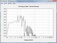
My suggestions would be along these lines, in the Wizard set the display to response, then:
- increase L45 until you equalize the dips around the first big peak (58Hz),
- decrease S3 to reduce the first peak (below 20Hz), and increase/decrease L23/L34 to even out the height of the first two peaks,
- decrease S2 to reduce the overall apmplitude of the peaks in the passband (I recommend to keep the compression ratio-Sd/S2-below 3:1)
- keep L12 as short as possible while not increasing the first dip (22Hz), this should improve the impulse response.
When you have a model that looks reasonable you still have the job to fold this into an enclosure. You may find, that you have to make several iterations of modeling and folding until you have something that is worth the effort of a trial build.
Hope this helps,
Regards,
Hi Graham,
Getting to 15Hz results in a very long horn with all the associated delay problems.
In general I like to use the 4 section model, it gives me more freedom to inspect the interaction between driver and enclosure, and while it is important to check for excursion and maxium SPL it is also useful to model @ the 1W level, and in 2PI space, for general comparisons.
My suggestions would be along these lines, in the Wizard set the display to response, then:
- increase L45 until you equalize the dips around the first big peak (58Hz),
- decrease S3 to reduce the first peak (below 20Hz), and increase/decrease L23/L34 to even out the height of the first two peaks,
- decrease S2 to reduce the overall apmplitude of the peaks in the passband (I recommend to keep the compression ratio-Sd/S2-below 3:1)
- keep L12 as short as possible while not increasing the first dip (22Hz), this should improve the impulse response.
When you have a model that looks reasonable you still have the job to fold this into an enclosure. You may find, that you have to make several iterations of modeling and folding until you have something that is worth the effort of a trial build.
Hope this helps,
Regards,
Attachments
Oliver
Thanks for your kind response. Trying to understand horns isn't easy as I have found out. Ideally I want a tall floor to celing horn with just one fold so I can keep the box narrow. This I guess would limit me to one driver. Floor to ceiling is 8 feet which would allow for approx 16 feet horn. I did think about a single 15" driver in each horn but am not too sure what 15" drivers would be ok to model.
The problem I have is my current set up is 2 15 cu ft FI Q18 ported subs with multi tune. I have a 12.5hz, 17.5hz and 21.5hz tunes along with sealed too.
Now I find my 17.5hz tune the best so a horn in that area would be fine. The winisd plot of my 17.5hz tune is showing 117db at 20hz and 120db at 30hz.
I want a horn that is going to beat that tune. I have the behringer EP4000 amp so power isn't a problem. Modelling the Q18's is just not realistic.
If you have any suggestions I would really appreciate your input and advice as what you think the best way forward would be and how easy it would be to beat those spl figures.
cheers again.
graham
Hi Graham,
It looks to me, that a single fold with a total length of 16' is not quite long enough for 17Hz. You also will have to allow for getting the box in and out of the room, so you are limited to about 88" height. The DTS-20 folding (from the patent drawing) comes to mind, it is about 18' long. It looks like Danley has gone to the multiple driver enclosures for the sub 20Hz market, e.g.: TH-SPUD (19') and DTS-10 (25'?). That looks like the way to go. There are just too many drivers available today") , e.g.: a pair of JBL GTO 1214 looks possible, as a starting point see:
, e.g.: a pair of JBL GTO 1214 looks possible, as a starting point see:
http://www.diyaudio.com/forums/subwoofers/160879-build-your-own-2x12-th.html
Regards,
It looks to me, that a single fold with a total length of 16' is not quite long enough for 17Hz. You also will have to allow for getting the box in and out of the room, so you are limited to about 88" height. The DTS-20 folding (from the patent drawing) comes to mind, it is about 18' long. It looks like Danley has gone to the multiple driver enclosures for the sub 20Hz market, e.g.: TH-SPUD (19') and DTS-10 (25'?). That looks like the way to go. There are just too many drivers available today
, e.g.: a pair of JBL GTO 1214 looks possible, as a starting point see: http://www.diyaudio.com/forums/subwoofers/160879-build-your-own-2x12-th.html
Regards,
Hi Graham,
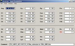
From your desired footprint (30" x 16") you get 480"^2 / 3097cm^2, assuming an internal volume of 600 Liter you get a height of 194cm; all that is net without driver volumes, and without wood.
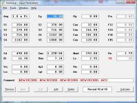
I'll attach a Hornresp input screen of a simulation I did a while back, don't even know if these drivers are still available, but this should be a workable Hornresp example.
The rest of the job will have to be up to you.
Regards,
From your desired footprint (30" x 16") you get 480"^2 / 3097cm^2, assuming an internal volume of 600 Liter you get a height of 194cm; all that is net without driver volumes, and without wood.
I'll attach a Hornresp input screen of a simulation I did a while back, don't even know if these drivers are still available, but this should be a workable Hornresp example.
The rest of the job will have to be up to you.
Regards,
Attachments
Oliver
I tapped in those details into my AV12 horn spec and came up with this.
How does this look like. It looks like you can have a max input power off 70 volts before going over max excursion.
How does this look like. I can get the LAB12 drivers here in the UK. They only have 13mm off excursion where as the AV12's have 23mm.
Just need to work out what readings you look at for measurements for the mouth and the throught.
cheers
Graham
Attachments
Hi Graham,
First one warning, before you cut wood for a specific speaker try to measure the Thiel/Small parameters for that speaker. Tapped horn dimensions are directly interlinked with the drivers parameters, and you can go badly wrong assuming that the manufacturers data is correct. If you have the correct data, your simulation looks fine to me. Tom Danley insists that ultimately you'll have to build and measure to see how accurate your simulation is.
All else being equal: the more excursion you can get, and the higher the maximum power handling, the more ouput SPL you can generate. It is being said, that Danley uses the MTX T915-44 in the Matterhorn. Some of the long throw car woofers give up a lot of efficiency, so that is something to watch for. But for infrasonic sound reproduction you need to move some air. You also always have that pesky price-performance ratio. The JBLs mentioned in Post #10 are right now leading in that department (on the smaller woofer end it's the MCM 55-2421).
As to the throat and mouth dimensions: S1 is actually the throat, but in tapped horn simulations I'm looking at S2 as the important dimension. A starting point for S2 is Sd/2 or Sd/3. When you look at the horn path in the SPUD and the DTS-10 the S1 is actually larger than S2. Much smaller, and the compression will get too high for the mechanical well being of the driver. In a 4-section TH S5 is the mouth, and a starting point is 2xSd. A squarish mouth aspect ratio seems to be preferable, I don't know of any testing on THs that has been published for mouth in e.g.: a slot like form. Basically the same holds true for the driver entry into the horn path at S2, unless the drivers are mounted as in the SPUD, or the DTS-10.
As to the length of the horn, you are looking at about the quarter-wavelength of the desired bottom frequency. So for 15Hz you are looking at 5.7m. As you must have seen by now in the Hornresp simulations you will need some additional length. Maybe we are looking for the driver back to driver front distance as the quarter-wave distance?
Well, I've gone on way too long, hope this helps.
Regards,
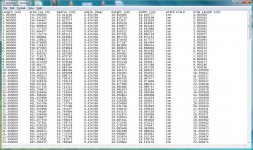
I just realised that to find out the dimensions off the horn you have to export the horn data. Oops!
Here is a pic to show the first section. I see there is a height and width dimension along with a length one. The length one makes sense but do I just take the height one along with the length one to be able to draw the horn.
I apologise for so many questions but I am a complete newb.
cheers
Graham
Here is a pic to show the first section. I see there is a height and width dimension along with a length one. The length one makes sense but do I just take the height one along with the length one to be able to draw the horn.
I apologise for so many questions but I am a complete newb.
cheers
Graham
Attachments
Hi Graham,
Lets see, when you are in the schematic diagram window you click on File - Export-Horn Data. Here you can choose the height of the horn at the S1-S5 areas, you can also pick the increments at which Hornresp calculates the cross-sectional areas, and you can set the flare, e.g.: to Uni or Exp.
The length is the distance from calculated step to calculated step (increment), the height is the data you entered (or accepted from Hornresp), and the width is calculated by Hornresp to correspond to the area at that point (height x width).
Just play with it, and I'll bet it'll make sense.
Regards,
Last edited:
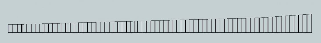
I'm a bit late, but this may help you some:
Mal-X horn folded? - Page 11 - Home Theater Forum and Systems - HomeTheaterShack.com
There is also a downloadable SketchUp file, with some steps laid out here:
Mal-X horn folded? - Page 13 - Home Theater Forum and Systems - HomeTheaterShack.com
Mal-X horn folded? - Page 11 - Home Theater Forum and Systems - HomeTheaterShack.com
There is also a downloadable SketchUp file, with some steps laid out here:
Mal-X horn folded? - Page 13 - Home Theater Forum and Systems - HomeTheaterShack.com
- Status
- This old topic is closed. If you want to reopen this topic, contact a moderator using the "Report Post" button.
- Home
- Loudspeakers
- Subwoofers
- Best way to learn Hornsrep