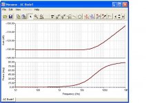
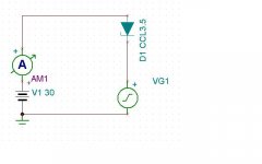
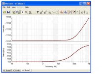
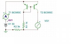
So, here are my results and test circuit for the Central Semi 3.5 mA CRD (CLD). I think it's pretty good, with constant current fading at about 20kHz and beyond. The voltage source VG1 is set for an internal impedance of 1k.
Attachments
Last edited:
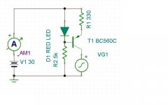
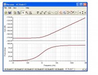
Here is the BC560C (hfe=800) in a ccs configuration. Good results also. The model for the LED comes from Cordell Audio. Current was set at about 3.4mA
Theres one aspect these results dont show, PSRR when introduced in real circuit. As good as the results look for example for the BC560C youll notice that in real circuit it will perform dismall, the problem being that the BC has low early voltage. This is essential for high PSRR so here you need a transistor as good as your vas, ie a video transistor with high VCE and low Cob. Alternatively the use of cascoded current source is the route to take.
Here is the BC560C in a current mirror configuration. I had to add the 3k resistor to cut down the current flow to about 4mA for each transistor.
I don't know which kind of transistor to use for CCS. I just grabbed something. Thanks for the tips.
I don't know which kind of transistor to use for CCS. I just grabbed something. Thanks for the tips.
Attachments
Theres one aspect these results dont show, PSRR when introduced in real circuit. As good as the results look for example for the BC560C youll notice that in real circuit it will perform dismall, the problem being that the BC has low early voltage. This is essential for high PSRR so here you need a transistor as good as your vas, ie a video transistor with high VCE and low Cob. Alternatively the use of cascoded current source is the route to take.
I didn't test for PSRR and thanks for the tip on which kind of transistor to use for the ccs. I'm having serious problems with my right hand now, so I can't do as much on the computer for a while.
Hi dirkwright
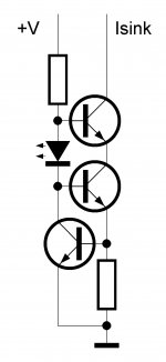
Please proceed, I'm just searching freq flat CCS. Can you please sim attached CCS?")
I'll try later. I'm on vacation and I'm having some serious pain in my right hand and arm. I banged my elbow and irritated the nerve.
Andrew, in the position of current source hfe s importance is basically nought or only in far second of priorities, this applies to main vas transistor as well. My fav current sources are same as vas, 1381 and comp are excellent choices.
In the case of current mirror hfe is first priority.
In the case of current mirror hfe is first priority.
Walt Jung wrote an article for Audio Express about current sources. I copied a good one and tested it. Even if -170dB is maybe not achievable in the real world, it sure does beat the pants off of most everything else. One concern I have is the phase shift which is well within the audio band.
His article here:
http://waltjung.org/PDFs/Sources_101_P1.pdf
His article here:
http://waltjung.org/PDFs/Sources_101_P1.pdf
Attachments
One concern I have is the phase shift which is well within the audio band.
His article here:
http://waltjung.org/PDFs/Sources_101_P1.pdf
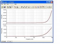
What you see here is the phase shift from the residual output capacitance of about 500fF becoming the dominant admittance around 1kHz and above. The ~ -170dB represents a low-frequency impedance of about 316Mohm.
Why would this be a concern? The issue here is what is the circuit into which such a source (or a better one, and you can do much better than this btw
) will be embedded? In the overwhelming majority of cases the rest of the circuit will have both much lower resistance and much higher capacitance, and so will set the response.Where, however, this reduction in output capacitance and conductance is helpful, is in reducing distortion due to voltage swing. Walt refers to "nonlinear capacitance" as a distortion mechanism, and makes the distinction between it and a "pure capacitance". Although virtually any known voltage-variable capacitance does indeed vary its capacitance with applied voltage in a nonlinear way, I like to simply say "voltage-variable" capacitance, since as to always qualify things with the "nonlinear" adjective can mislead a student to suppose that a linearly variable capacitance would not generate distortion. And this is quite incorrect.
So when you have reduced the capacitance over a useful frequency range to as little as the apparent half a picofarad, its variation with voltage becomes correspondingly less important as a distortion mechanism. And this is a good thing
Note that this is achieved by returning the upper gate to the lower source, which pumps the upper drain-gate displacement current back into the whole works. The effectiveness of this is enhanced the higher the value of the resistor compared to (roughly) the reciprocal of the lower device's transconductance, as the current from the upper gate divides in accordance with a normalized weighting function.By adding an additional cascode device (and sacrificing more voltage swing), with the uppermost cascode device's gate returned to the first cascode device's source, you can get even lower output capacitance. Remember though that each successive device must have a higher pinchoff voltage, or some external bias needs to be applied. This can be a battery, and will last the shelf life as the drain is completely negligible.
Brad
Cascoding the cascode...makes horrendous circuits possible. but again the circuits where you can use them are much inferior.
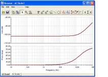
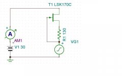
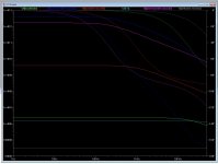
here is a plot of differnt current sources (led/Bjts and Jfet) and their output impedance's.. Common is that a jfet cascode or dual JFet cascodes really makes things a lot better....
here is a plot of differnt current sources (led/Bjts and Jfet) and their output impedance's.. Common is that a jfet cascode or dual JFet cascodes really makes things a lot better....
Attachments
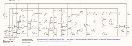
subcircuit optimization in isolation is pointless - what is the VAS driving - even a triple EF output will have lower, more nonlinear input Z, pre-driver Q alone have more Ccb
and a practical limit of active techniques is the package/wiring/pcb trace parasitic C
output stage distortions, particularly Class AB gm modulation will dominate even with fairly "primitive" VAS
and a practical limit of active techniques is the package/wiring/pcb trace parasitic C
output stage distortions, particularly Class AB gm modulation will dominate even with fairly "primitive" VAS
Walt Jung wrote an article for Audio Express about current sources. I copied a good one and tested it. Even if -170dB is maybe not achievable in the real world, it sure does beat the pants off of most everything else. One concern I have is the phase shift which is well within the audio band.
His article here:
http://waltjung.org/PDFs/Sources_101_P1.pdf
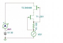
Yea, that is the FET cascode in the model I published. Stiffest of all, but not as linear. It could be some really really Ghz FETS would be the perfect choice.
Cascoding the cascode...makes horrendous circuits possible. but again the circuits where you can use them are much inferior.
here is a plot of differnt current sources (led/Bjts and Jfet) and their output impedance's.. Common is that a jfet cascode or dual JFet cascodes really makes things a lot better....
I was limiting it to things I would actually put in a circuit, about 2 active devices. With enough parts, I am sure one can model anything. Maybe OK for a new design, but not to retrofit.
subcircuit optimization in isolation is pointless - what is the VAS driving - even a triple EF output will have lower, more nonlinear input Z, pre-driver Q alone have more Ccb
and a practical limit of active techniques is the package/wiring/pcb trace parasitic C
output stage distortions, particularly Class AB gm modulation will dominate even with fairly "primitive" VAS
Exactly. Just the single FET is good enough that the next biggest problem is elsewhere. What would be beneficial is to identify bjt or fet devices that happen to behave well as the ccs for either very low current, i.e IPS, or a bit higher in the feedback pair configuration for the VAS.
- Status
- This old topic is closed. If you want to reopen this topic, contact a moderator using the "Report Post" button.
- Home
- Amplifiers
- Solid State
- Best VAS?