Anatech, the 12AX7 is useful, but not for low gain, high drive line amps. Your 'highly trained engineers' had a job to do, and if you'd be so kind please tell me why they did what they did? as in why are there 12AX7 line amps?
And to T-S, after nearly 30 pages of hearing that the amp of yours is a difficult load, why on earth are you building something that is so far from capable of driving it well?
cheers,
Douglas
And to T-S, after nearly 30 pages of hearing that the amp of yours is a difficult load, why on earth are you building something that is so far from capable of driving it well?
cheers,
Douglas
Anatech, the 12AX7 is useful, but not for low gain, high drive line amps. Your 'highly trained engineers' had a job to do, and if you'd be so kind please tell me why they did what they did? as in why are there 12AX7 line amps?
And to T-S, after nearly 30 pages of hearing that the amp of yours is a difficult load, why on earth are you building something that is so far from capable of driving it well?
cheers,
Douglas
...because everyone that built one has very good things to say about them...those that don't have not built one nor heard one, so really they are only speaking from their own hypothesis...which has not even made it to the theory stage...
...Regarding Anatech aka Chris...he has been most helpful which has been rare in this thread consistently....so I would appreciate it if those who insist on a negative stance on this before it is even tested just leave him be as he has shown a genuine attitude of regard and of sincerely being helpful...above the herd mentality....cheers
...because that is what I have decided to do based on reports of very good sonic results from those who have done so....
So this:
"Output impedance would need to be 100 ohms or lower (all good solid state high end preamps can do this easily) ...It is always good engineering practice to have at least 10 times lower driving impedance for Audio. 100 times is better."
was all BS then, right?

...and if I end up being wrong in my endeavours...so be it...I am wrong for myself and have learned something....however...if I am correct...then I have gained also...and those who tried so hard to inhibit this from moving forwards...will have learned something...either way...it's a learning experience....so if someone does not like it....don't comment....keep it to yourself....I am going forward with this regardless of the outcome....and I appreciate the input and interest from Chris who has shown good attitude and character in my venture...successful or not...
Best value for money in my book would be 5687 (or use JJ ECC99) into a Lundahl Transformer, model LL1660; a very versatile unit and user configurable transformer. I would suggest 4.5:1 gapped for 10mA, run the tube (one dual triode with one section per channel) 150V plate and 10mA, just as a starting point.
A very sensible and good sounding suggestion. I would perhaps go for the 18mA gap, as inductance is sufficient and allows for 6N30 tests at higher currents.
Cool nick too. Ex Safer?
Hi Guys,
If you want to drive a cable and following input stage, you need a low impedance output stage in the source equipment. I think we can all agree on that point. There are a few ways to go about this, one being the use of feedback to lower output impedance. The 12AX7 provides gain so that this can be done. You can also use cathode followers and transformers, hopefully with some feedback.
I objected to the statement that Douglas made earlier,
We tend to do things differently that we did in the 50's and 60's. That doesn't mean the earlier practices were wrong. Yes, you can pull out examples of bad engineering from any era, so let's not bother looking at those (eg, Jadis).
I don't think it's particularly wise to attempt to drive cables and the following input stage with an open loop design, but that's just me.
-Chris
If you want to drive a cable and following input stage, you need a low impedance output stage in the source equipment. I think we can all agree on that point. There are a few ways to go about this, one being the use of feedback to lower output impedance. The 12AX7 provides gain so that this can be done. You can also use cathode followers and transformers, hopefully with some feedback.
I objected to the statement that Douglas made earlier,
Okay, so you disagree with me. That doesn't mean you are correct either. I don't know if there will be tone controls, or filters either. The 12AX7 or 12AT7 will provide the gain required for these circuits, maybe in conjunction with the output stage.TS, let me be blunt; the 12AX7 has *NO* business in a linestage. None.
We tend to do things differently that we did in the 50's and 60's. That doesn't mean the earlier practices were wrong. Yes, you can pull out examples of bad engineering from any era, so let's not bother looking at those (eg, Jadis).
I don't think it's particularly wise to attempt to drive cables and the following input stage with an open loop design, but that's just me.
-Chris
Hey Chris ... thanks for your input ... however no tone controls, no filters - just pure amplification of source to amp to speakers...The less in the path of the signal source --- the better IMO
...I am even wondering how to go about input rca's and relays...I don't want to compromise the sound, so I like to solder everything as practical as possible... maybe all rca's connected together with only one signal source switched on, or really good relays with gold/silver contacts that are highly conductive with large contact areas --- but non-oxidating...
...I am even wondering how to go about input rca's and relays...I don't want to compromise the sound, so I like to solder everything as practical as possible... maybe all rca's connected together with only one signal source switched on, or really good relays with gold/silver contacts that are highly conductive with large contact areas --- but non-oxidating...
Last edited:
Hi TS,
They make gas filled relays for signal use. Very low current signals tend to have problems with relays types that you're talking about. The gas used is normally nitrogen, so contacts don't oxidize. Look for signal relays for telecom or instrumentation. Those are the once you want. 2 form c.
Input jacks are easy. Again, you can buy really expensive ones, or more moderately priced jacks. Just make sure the grounds are isolated from the chassis ground and create your own signal to chassis ground point where you want it. If you have a phono stage, right at the jacks there. If not, pick an input and ground it there.
As for signal path, sometimes tone controls are good, and they aren't all bad. It comes down to personal preference. I wouldn't put them in, but I tend to leave the controls flat on preamps I have with tone controls. You can always use a bypass switch or relay to take them completely out of circuit when you aren't using them.
Put things into perspective. If you knew how many connections and tone controls, gain stages and all that the signal does go through in the studio, you might take a more pragmatic view about how your preamp will go together. Relax, design a preamp you can live with and don't sweat the tiny details that don't matter much at the end of the day. One thing that might help is if you stop looking for "the best" and concentrate on making good choices with good parts. Done that way, your preamp will work extremely well and you'll be happy with it.
You're already ahead of the game. You have a good power supply for starters. Many older preamps didn't use regulation at all. Take care with your build and use common sense in circuit placement. You'll be fine if you do that.
-Chris
...well,Peter Stein spent some time with me instructing me on changing the Z-value to 68K on the ME550 ... now its much more compatible with more pre-amps...
...quite a helpful fellow...Its just a matter of snipping 2 x L/R resistors and reversing the polarity of the red input channel. You have the option of having the ME550 running with a input Z-value of 1kohms, 15kohms or 68kohms - depending on which resistors you snipp...
...quite a helpful fellow...Its just a matter of snipping 2 x L/R resistors and reversing the polarity of the red input channel. You have the option of having the ME550 running with a input Z-value of 1kohms, 15kohms or 68kohms - depending on which resistors you snipp...
Hi TS,
That's fabulous! Problem solved painlessly.
It would seem that the unusual low input impedance isn't necessary after all.
-Chris
LOL - yes, I feel spared a lot of to-ing and fro-ing - Peter Stein the designer is a genuinely helpful person ... sounds quite good, you can tell the difference, detail, airiness, soundstage...and that is with the Matisse based 'Guanzo' valve pre-amp/buffer...
...now to focus on building the JP200...
A 15k Ohm input load can be tolerated by a remarkably large number of circuits of traditional tube style. Go a little further, with some of them and have a listen. A 12B4 triode with a mu-follower equipped CCS comes to mind. Something rather like this:
Epifania Info
cheers,
Douglas
Epifania Info
cheers,
Douglas
LOL - yes, I feel spared a lot of to-ing and fro-ing - Peter Stein the designer is a genuinely helpful person ... sounds quite good, you can tell the difference, detail, airiness, soundstage...and that is with the Matisse based 'Guanzo' valve pre-amp/buffer...
...now to focus on building the JP200...
I think in Audio many things aren't *necessary* strictly speaking. It was done to extract better sound quality within the framework of his design parameters.. which included the preamplifier. If you change that parameter (for example, with a tube pre with a much higher output impedance) then you are going to choose what was chosen in the end - and perhaps, for you, the sonic benefits of additional distortion/compression/harmonic enrichment afforded by your tube amp will outweigh the slight loss of quality that would have attended driving the thing with a sub-optimal, in terms of impedance, stage in it's original configuration - all other things being equal.
Enjoy, you do have a particularly good amp, and yes in my dealings with Peter I have found him to be the perfect gentleman, kudos....what an amazing sounding amp !! Elvis gospel songs sound fabulous !!
...that Z-value mod just opened the sound up...
Dan.
You should post a sketch or something.. you know, for posterity. 8) It might save Peter some work next time someone wants to know. Just an idea.
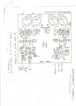
That sounds like a good idea. This is for the ME550 Series I. This is what I did for mine as per instructions and it worked for me. (NOTE: Do so at your own risk or consult further with an ME technician)
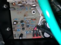
First clip the relevant resistors as per diagram (see attachment) depending on whether you wish to have Z-output of 15Kohms or 68Kohms.
You find the exact spot for one side of the amp; clip those resistors (see photo) and then turn the diagram 180 degrees and do the same on the other side in the exact same spot.
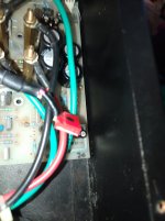
On the red input plug, the red wire on flat plug (from circuit board leading to RCA input plug) has a white line on the side of it, and that should be reversed so that the red wire with white line plugs into the part of the circuit board markings (180, E, 0) where it is plugged into, is '0'. This is also verified by ensuring the green dot on the flat side of the plug is facing the chassis of the amp (see photo)
(On the black RCA leading to the flat input plug on the circuit board, I noticed the red wire with white line on the side of the flat plug going from circuit board to RCA input plug was at '0', and it appears it should be there by default. I did not see a green dot painted on that side however. I don't think there was meant to be one there for the left side as it is on zero already, however I checked to make sure).
An excerpt attached as pdf from the manual called 'Wiring for Common Earth Systems' explains things more.
...as I said - this is what I did per instructions and it worked for me ...
Attachments
Last edited:
Peter Stein also said when I asked him about any possible degradation of sonic quality if the Z-value was changed to a higher value ie 68Kohm:
"Sound quality has more to do with how the input of the amplifier gets its signal - the standard arrangement optimises both cable and environmental issues (as long as preamp driving it is commensurate quality and performance as I previously mentioned).
Sound quality may be degraded if these issues are affected by less than ideal factors - one will be that cable quality will be much more influential, and how the preamplifier (if more than a few hundred ohms output Z) reacts to both the cable and the environment (read interference of various kinds) - this is outside the influence of the amplifier input, as the amplifier really can't fix damaged audio - it just amplifies what it sees!"
...and
"...no sound degradation from the amplifiers perspective - just the presentation of the signal - the potential and effective issues are outside the amplifier.
Adding an output transformer is a poor choice as transformers add significant distortions and will almost always pick up noise."
...and
".... If you don't like what you are hearing - even after significant experiments - I would suggest you know how to go back to square one"
A 15k Ohm input load can be tolerated by a remarkably large number of circuits of traditional tube style. Go a little further, with some of them and have a listen. A 12B4 triode with a mu-follower equipped CCS comes to mind. Something rather like this:
Epifania Info
cheers,
Douglas
...looks good --- however quite a price tag on that...
...I would rather modify the JP200 or something similar...I know some have modified it so it ends up with less gain etc...Since I am new to this, I need to see how things fit together and work. The ideal Z-value would be (as I understand it) <680ohm for the ME (or 150ohm if using 15Kohm option).
...Since the Rotel RN990BX is 33Kohm, its ideal Z-value would be <330ohm which would work for both amps...
...if there was a painless way to reduce the Z-value of the JP200, I would then do so - but without compromise to the sound. Peter Stein said: "...Adding an output transformer is a poor choice as transformers add significant distortions and will almost always pick up noise."
I am amazed that the Guanzo sounds so good with both amps @ $50...I only got them as pre-to-main buffers for integrated amps, however not having a pre-amp I decided to used one temporally as a preamp and am quite surprised at the result. With the Rotel RB990BX and the ME550 it works significantly well with them - not sure of the output Z-value, one source that was a 3 tube version gave 600ohm, while the original Mattise it was based on, gave 4Kohm. It is very difficult to get specs from the chinese I noticed...as I asked...
This is what appears to be the original 'Matisse' preamp, but with MC/MM sections, while the Guanzo appears to have focused only on the linestage part of it, or based - their version on it...: MATISSE AUDIO ON-LINE / Valve Hifi / Reference Pre-amplifier
Last edited:
- Status
- Not open for further replies.
- Home
- Amplifiers
- Tubes / Valves
- Best Valve pre-amp match for ME 550 amp