Wavebourn said:

Me!
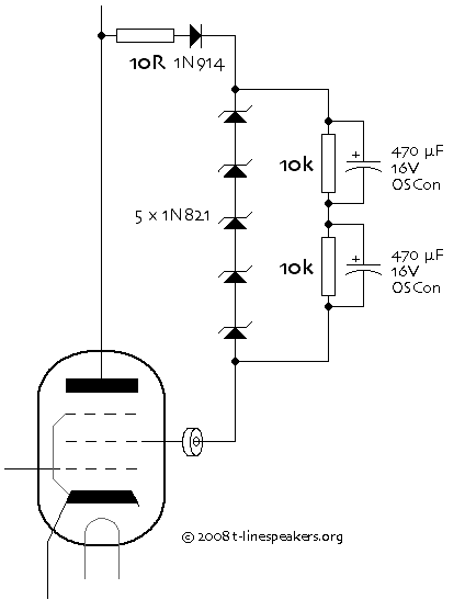
How do you like my triode load?
It is like a very clean choke with very big inductance!!!
Very high DR on AF, very low DR on DC, so voltage on plate is stable and lower B+ voltage is needed!

Can you design something better?
That looks interesting, but it's buried OT here. Should have a separate thread or in a thread discussing CCS's.
Sheldon
Sheldon said:
That looks interesting, but it's buried OT here. Should have a separate thread or in a thread discussing CCS's.
Thank you.
I was joking in response to double meaning... Sorry for OT...
Second meaning of the message was the entire picture drawn in LTSpice.Look at this page:
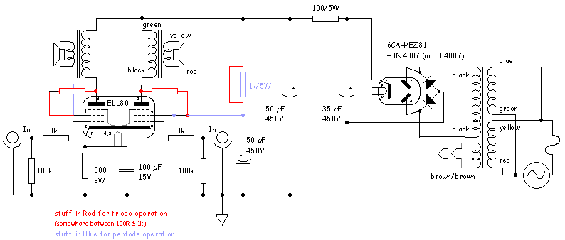
http://www.tubelab.com/SimpleSE_schematic.htm
The schematic at the top was done with Visio Pro, the bottom schematic was done with Eagle (PC board schematic only).
Visio makes a prettier schematic, but you have to give Microsoft a bunch of money for a drawing program. It can also be used for basic mechanical drawings. I use it for planning out the layout for all of the large components on an amplifier chassis.
Eagle makes an acceptable schematic, and you can use the schematic to lay out a PC board. There is a freeware fersion that will do single page schematics and small PC boards. The full version that does multi tube designs is not cheap either. I have seen a budget designer do several small PC board designs with the freeware version and then paste them together with a cad program to make a large board.
LT spice will make acceptable schematics (previously shown CCS - triode schematic), but some symbols do not exist. I use it for simulations only, but it is free.
For my PC boards and web pages I have to use the full version of both programs.
I use Linux a lot, and they do have a bunch of free stuff, that's where I got to using dia a while back.
I'd hate to pay for something like Visio, too.
Anyway, for any Linux users out there, there's a free app similar to Visio called Kivio.
For Windows users, if you get the free Open Office suite (a free alternative to Microsoft Office), it includes the "Draw" program.
Now in anticipation of using dia in Windows:
I can take any one of your pro schematics, even ones made with visio or any random pic I find on the web, in jpg or gif format, etc., copy a small section of it, like a one tube section, and create my own library of these sub pictures, using an app like Irfan View where you can crop, save and rename a portion of a big pic as "save as", like "triode.gif" for example.
Then I can use dia and insert any of these on my palette, stretch or shrink them, and then insert the lines I need. Like I said it does have some basic stuff like resisitors, capacitors, coils, ground, diode, transistor, speaker symbol, etc., already built in.
I'll have to do something with this soon and post a demo.
I hadn't thought to try Open Office (great program btw, makes PDFs too). I think I'm gonna try it this weekend, see how well it works for schematics.
radtech said:I have yet to find a schematic cad program that will draw a really good quality schematic, most of them are too busy trying to be all things to all people... generating netlists and spice files and board layouts.. I just want a simple cad program that will draw a nice looking schematic, nothing else.
I use VectorWorks. Simple on the surface, with a huge amount of depth. Not real cheap thou -- unless you can get the student price. I have developed my own library of tube symbols over the last 10 years, slowly evolving them into my own style.
dave
planet10 said:
I use VectorWorks. Simple on the surface, with a huge amount of depth. Not real cheap thou -- unless you can get the student price.
Yeah, a little more than I'd be willing to spend.
I did a bit of testing with Open Office, here are my first impressions:
One really nice feature is the Gallery. Create a new theme, select a folder full of images, click 'add all' and you've got your images in a gallery above your drawing, all ready to drag-n-drop.
The biggest problem I've found is drawing lines. I'm having a tough time getting them to line up with the component images. Sometimes it looks like they're lined up when I'm zoomed in, but when I zoom out to normal size they're not. This could be it's downfall if I can't find a solution.
I'll mess around with it over the weekend and if I get it working good I'll post an example image.
I haven't had too much time to play with Dia yet, but one good feature it has along thse lines, is a "snap to grid" function which can be set as default. The background of the drawing has a grid, and it helps a lot, and keeps things neat. By snapping to grid, the lines you draw always stay right in place. Hopefully this weekend I will mess with it some more.
It installs fine in XP or Linux, but I had a problem in Windows 98 (I have 5 desktop computers here with several operating systems).
It wouldn't install in 98 (wizard problem), but I made a CD of the stuff in program files/dia from my XP box, and copied that to my 98 computer, and it worked.
It installs fine in XP or Linux, but I had a problem in Windows 98 (I have 5 desktop computers here with several operating systems).
It wouldn't install in 98 (wizard problem), but I made a CD of the stuff in program files/dia from my XP box, and copied that to my 98 computer, and it worked.
- Status
- This old topic is closed. If you want to reopen this topic, contact a moderator using the "Report Post" button.
- Home
- Amplifiers
- Tubes / Valves
- best schematic designer for tubes?