Best Grounding [SOLVED]
Hi,
I have built a complete DAC, with, several PSU's, USB interface, DAC and i/v converter.
It works wonderfull, but a strong buzz is present.
If I joint points A or B and C, then hum is smaller but something is here, noise is not gone totally.
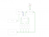
Somebody can see a better Grounding Scheme?
Thanks in advance.
Hi,
I have built a complete DAC, with, several PSU's, USB interface, DAC and i/v converter.
It works wonderfull, but a strong buzz is present.
If I joint points A or B and C, then hum is smaller but something is here, noise is not gone totally.
Somebody can see a better Grounding Scheme?
Thanks in advance.
Attachments
Last edited:
Hi,
I have built a complete DAC, with, several PSU's, USB interface, DAC and i/v converter. It works wonderfull, but a strong buzz is present.
Can you post some more info, photos, schematic?
The ground loop may be through the I/V converter. Can you try a separate +/- 9V supply (having its own ground) for the I/V?
Even a pair of 9V batteries for a short test would work, if you don't have any other supply available.
Disconnect completely the other 9V supply (including its ground) from the I/V.
Last edited:
Can you post some more info, photos, schematic?
The ground loop may be through the I/V converter. Can you try a separate +/- 9V supply (having its own ground) for the I/V?
Even a pair of 9V batteries for a short test would work, if you don't have any other supply available.
Disconnect completely the other 9V supply (including its ground) from the I/V.
Thanks rayma.
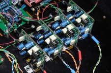
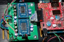
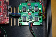
Every +5V reg. is a Jung SuperReg
USB Interface is a JLSounds Xmos with Reclock (JLSounds Oscillator) with Crystek 44 and 45 MHz.
+/-9V and +5V PSU for USB are standard LM317/LM337 adjustable PSUs
DAC is PCM1704 in NOS mode drive directly with USB interface.
I have another bipolar PSU for fed I/V converter
I will try when were possible.
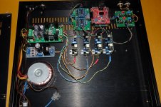
You may have lots of ground loops through the 5V regulators (and elsewhere, possibly). These loops are near the mains transformer. A toroid has low external magnetic flux, but not zero external magnetic flux. Check that each 0V connection has one and only one wire path back to the reference point.
You may have lots of ground loops through the 5V regulators (and elsewhere, possibly). These loops are near the mains transformer. A toroid has low external magnetic flux, but not zero external magnetic flux. Check that each 0V connection has one and only one wire path back to the reference point.
Reference point?
I have not Earth-chassis ground point.
On the other hand, I believe it is impossible to compliment with "one and only wire path" with several PSUs connected to same GND in another pcb. Always will be several GND paths.
Curiously, when I connect points C and D, buzz is almost gone, and I have added a new path to GND, so aparently this contradicts your claims.
You can see how adding a new path to gnd has lowered noise in the pdf file attached.
thanks DF96.
Attachments
There must be some point which you consider to be the reference point. This is because all voltages, whether DC or signal, only exist with respect to some other point. The reference point is not necessarily connected to the chassis or incoming mains ground, although often it is. Whether you have considered it or not, your circuits will have reference points but they may not all be at the same potential - this is a common source of buzz.LuisMCP said:Reference point?
I have not Earth-chassis ground point.
You are probably right, which is why that arrangement is generally a bad idea.On the other hand, I believe it is impossible to compliment with "one and only wire path" with several PSUs connected to same GND in another pcb. Always will be several GND paths.
I haven't claimed anything, just describing good design practice. If adding yet another ground connection improves things then the issue might be injection of charging currents into ground connections. Make sure you take the output from any PSU from the 'clean' end, well away from the rectifier/reservoir cap loop.Curiously, when I connect points C and D, buzz is almost gone, and I have added a new path to GND, so aparently this contradicts your claims.
Last edited:
You are probably right, which is why that arrangement is generally a bad idea.
I don't know another way of connecting several psus.
Do you?
If adding yet another ground connection improves things then the issue might be injection of charging currents into ground connections. Make sure you take the output from any PSU from the 'clean' end, well away from the rectifier/reservoir cap loop.
I think that added path did a small loop in size. With a GND plane, currents has infinite paths, but they take the shortest path because minimizes electromagnetic fields (EMF takes work to make it) and hence, induced noise.
Did I read you right that chassis is not tied to ground? If so, why not try a clip lead from chassis to ground.
My power input has not Earth plug, only Live and Neutral wires.
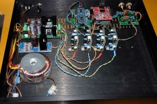
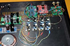
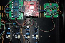
wires between Analog Output of DAC and I/V Converter, are extremely sensitive to noise. Moving these a few milimeters, and noise changes very much.
At this moment, i/v converter and DAC are at 12 cm long, and I think that if I move i/v to the nearest ubication, noise will gone greatly.
At this moment, i/v converter and DAC are at 12 cm long, and I think that if I move i/v to the nearest ubication, noise will gone greatly.
You will want to sort out the safety grounding of the chassis, what you have built is NOT a class II (Double insulated) appliance so it needs a mains earth to be safe (This is WAY more critical then a bit of hum).
The wiring between the current output DAC and the I/V stage is stupidly sensitive to magnetic fields, it is after all a current loop. If the signals are differential (They usually are with modern parts) then twisting each pair will help, screening may help but depends on the I/V stage having sufficient phase margin.
//edit
Just noticed we are talking a old single ended ladder part, makes things harder.
I would reference the I/V board signal reference to the DAC board (and assuming you cannot separate this from the power ground for that board, would make this a low impedance connection with the current outputs tightly twisted with it (Maybe even a screened pair or something).
Seems to me that the DAC board is pretty much the star point in this thing, and that the current arrangement creates a monster loop all the way around the PSU(s) -> DAC -> I/V -> PSUs...
I will admit that my first impression of the build is that it is a ratsnest and would have been surprised if it didn't hum.
Regards, Dan.
Last edited:
I will admit that my first impression of the build is that it is a ratsnest and would have been surprised if it didn't hum.
Regards, Dan.
oh! thanks!

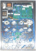
Is that set of three thick wires from the DAC to the I/V board the current outputs by any chance?
If so, epic fail, they are about a mile long and run completely unscreened under the fast digital of the USB interface card (The I/V card power ground then finishes the ground loop which is somewhat large.
Use a screened pair here, or better fix your chassis layout to put the DAC next to the I/V board, I2S is actually quite robust, the DAC current outputs not so much.
Worrying about shiny power regulators before you have the basics down strikes me as foolish, especially as I would bet modest money that those tiny twisted pairs you are so fond of are dropping so much voltage as to make the shiny regs largely pointless.
I highly commend getting a copy of Ott "Electromagnetic Compatibility", for that the problem really is.
Oh, and fix that safety ground first.
Regards, Dan.
Is that set of three thick wires from the DAC to the I/V board the current outputs by any chance?
Build is not definitive. It is a first try. I never built nor "cable lacing" if It is not completely tested. If I must to move some part or circuit, premature "cable lacing" is stupid. First test, rearrange, fix, and when all is ok, then make things looks better.
If so, epic fail, they are about a mile long and run completely unscreened under the fast digital of the USB interface card (The I/V card power ground then finishes the ground loop which is somewhat large.
Yesterday I saw that the problem was this cable. I thougth in two different solutions: move I/V closest to DAC or shielding the cable. I'll go for easiest solution.
Worrying about shiny power regulators before you have the basics down strikes me as foolish, especially as I would bet modest money that those tiny twisted pairs you are so fond of are dropping so much voltage as to make the shiny regs largely pointless.
Current demand of DAC are very small, 10mA on positive input and 40 mA at most in the negative (as I can remember). 26 awg with some 5-6cm long have very low resistance and with these low currents, dropping voltages may be ... some micro-volts? I don't mind.
Oh, and fix that safety ground first.
Regards, Dan.
The higher voltage in secondaries is 9VAC and a short run for 230VAC.
mmmmm... I have the power plug without earth ground pin and I am very lazy to drill the chassis for a new plug with earth safety pin.
Regards.
Luis.
wires between Analog Output of DAC and I/V Converter, are extremely sensitive to noise. Moving these a few milimeters, and noise changes very much.
At this moment, i/v converter and DAC are at 12 cm long, and I think that if I move i/v to the nearest ubication, noise will gone greatly.
The I/V convertors would be better next to the DAC.
The higher voltage in secondaries is 9VAC and a short run for 230VAC.
mmmmm... I have the power plug without earth ground pin and I am very lazy to drill the chassis for a new plug with earth safety pin.
Regards.
Luis.
I would suggest you read up on electrical safety, as to you comment above it is disgusting...to lazy to care about someone's life

The site for electromagnetic compatibility...
http://www.hottconsultants.com/
I have the power plug without earth ground pin and I am very lazy to drill the chassis for a new plug with earth safety pin.
As long as it is only your own life that is at stake, and no-one else ever goes near the thing...
- Status
- This old topic is closed. If you want to reopen this topic, contact a moderator using the "Report Post" button.
- Home
- Source & Line
- Digital Source
- Best Grounding