What bugs me is that the Revox is a 5 channel AV amp, with 5xTDA7294 and only a 300VA toroid.
G'day my friend from Lisboa! It would worry me too slightly given the price of the amp but I am currently listening to my OPA627 buffered IGC with just 80VA per channel and I cannot fault the sound. I think a bit more VA is better but not essential.
Hi Nuuk!
Well, I suppose it will depend on the transformer voltage.
If using a 2x18V trafo, the amp will give less output power and will demand less current from the PSU.
If you use a 2x22 or 2x24V trafo, you may get into trouble with low VA ratings.
The bass will suffer, and the amp may play well only with ultra-sensitive speakers.
I have a very small amp (my portable amp ), with two OPA548s, and a 2x12V, 2A trafo.
It plays surprizingly well, but I think it's because of the low voltage.
With around +/- 15V PSU the amp must be delivering some 10 watts RMS...
Well, I suppose it will depend on the transformer voltage.
If using a 2x18V trafo, the amp will give less output power and will demand less current from the PSU.
If you use a 2x22 or 2x24V trafo, you may get into trouble with low VA ratings.
The bass will suffer, and the amp may play well only with ultra-sensitive speakers.
I have a very small amp (my portable amp
), with two OPA548s, and a 2x12V, 2A trafo. It plays surprizingly well, but I think it's because of the low voltage.
With around +/- 15V PSU the amp must be delivering some 10 watts RMS...
Re: humm
J-P,
Thanks for the good words, first.
You can use a devider at the front of the GC to decrease the sensitivity. If you want you can use a switch to turn the devider on or off depending on the type of speackers you use.
uvodee said:I made a stereo set, first try = great, had to sell it because my first guest wanted to take it home.
second set I had problems , turned out to be a problem with the ground! (thanks for the awesome assistance Gregc.
I just finished my third set again using the LM3875's some different brand of components in caps and resistors, but my ears don't want to go along I think, it seems no different in sound to me. One problem is that i cannot connect them to my 70's Epicure speakers = too sensitive, I can only regulate the volume within 1/4 of the track, and then the sound becomes tooooo loud. When using other speakers like Pioneer of Audax there is no problem
I have components for 3 more and then I am going to start new speakers with the Jordan X92S
Right now I am using transformers from Apex, one (200 VA) for both chips and hear no irregularities.
I must say that I was quite impressed the first time using them, There were noises from the recording coming out of the speakers that I had never heard before, expecially when listeing to live classical recordings.
Jean-Pierre
After that I am starting with the Lm3886 .....
J-P,
Thanks for the good words, first.
You can use a devider at the front of the GC to decrease the sensitivity. If you want you can use a switch to turn the devider on or off depending on the type of speackers you use.
Luke said:
Hi Peter,
is that the one on the LM3875 datsheet, top of the page, fig 1.
Is that really your preferrred clone?
cheers ab
It's basically like that, with most components removed, except for 3 resistors and 2 caps
http://www.diyaudio.com/forums/showthread.php?s=&postid=265546#post265546
PS: Doesn't matter that cheap is different in the drawing.
Attachments
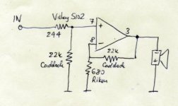
The above schematic is good, but I wouldn't recommend it anymore. My current version looks like this. Note that polarity of the speakers is not mistaken. For some reason the sound is better out of phase Also, 244 Vishay is optional. I chose this value as it can be bought cheap ($3) from a forum member.
Also, 244 Vishay is optional. I chose this value as it can be bought cheap ($3) from a forum member.Attachments
Yes but...... this schematic is so different that the other !!
Do you have the complete schematic for this amp ?? Because I don't see the value of the pot on your draw.
And what is 244 Vishay ?????
What is the value of the cap at the input ???
If you have the entire schematic, I will understand more how to do the circuit....
Thank you Peter Daniel
Do you have the complete schematic for this amp ?? Because I don't see the value of the pot on your draw.
And what is 244 Vishay ?????
What is the value of the cap at the input ???
If you have the entire schematic, I will understand more how to do the circuit....
Thank you Peter Daniel
 .
. .
.I'm sure the chaps at National will be very amused that people spend twice as much on resistors for an Overture amp, than they do on the silicon.
As an electronics engineer I'm often called upon to increase the performance of a design and spend as little as possible to do so - this is almost inevitably done by paying special attention to power supplies and reducing wiring length, both critical for RF receiver/transmitter design.
Of course the beauty of the GC is the short signal path and the intimate thermal tracking and matching of all stages on on the chip die; but little attention is paid to the performance of PSU.
If you read (for example) page 10 of the National LM3875 data sheet there is neat graph of PSRR vs Freq. The PSRR at HF of this device is not brilliant and just adding a couple of small caps won't cure the problem, and certainly not poly-whatevers. The physical size and lead inductance will not help and the ESR is not wonderfully low on these parts - on the design we have been working on we use an active +/- supply with some MLCC type caps right up against the IC - the ESR on these is at it's lowest between about 10-150KHz, these are SMD's and 1812 physical size. Close by are some low esr YXF capacitors that DON'T cost a fortune.
And for the resistors we are using 0.1% 1206 resitors. A little on the expensive side at $0.30 each, but we only use them in the feedback network and the input impedance termination - the very low TC% on these parts is probably more important than the accuracy (typical resistor is something like 200ppm/C and these are 25ppm/C, for $0.80 each when can get 10ppm/C) for thermal distortion (gain changes as the resistor heats or cools due to voltage across it) - if you don't believe it measure the gain after a load bass note!
The Caddocks I'm using are MK132. This is the whole schematic I have at the moment.
The value of the pot shouldn't be more than 50k and 20k would be better. In this case you wouldn't need shunting resistor.
I'm noy using a cap at the input, but anything more than 4u should be fine. The Vishay is 244ohm, but you can use other value (200-400ohm or so), other resistor, or you might not use it at all.
For complete schematic check the previous posts.
Out of phase connection of the speakers is my current preference. Yours might be different
arold19 said:You don't need 0.22 ohm resistor at the output ??
And you don't need 1uf cap between the V+ and the V- ???
Never noticed they were needed.
OK....
If I have a 20k pot, You say that I don't need the "shunt" resistor..... I don't know what is this resistor ???
It is not necessary to have a 4,7 uf cap ????
The only schematic I see in the previous post is this one...
This schema is complete or not ???
I just have to put a pot of 20k at the input and the power supply and the amp is ok ???
Attachments

Shunt resistor is the 22k from +input to ground.
If your source produces very low DC offset or has capacitor at the utput, you don't really need the cap at the amp's input. If you not sure about it, better use it.
So the schematic is complete. Just add a pot and a power supply.
More complete schematic is posted here: http://www.diyaudio.com/forums/showthread.php?s=&postid=301095#post301095 however I don't find it that appealing
Greetings Gaincloners
After spending MONTHS reading all the available posts I have nearly got all the parts together to build my 'Patek' clone - special thanks got to Peter Daniel for all the inspiration his amps and design choices have given me.
I would be greatful if someone could clarify for me that what I am about to build is technically correct before I embark on the construction of my amp.
I am using Peter's schematic with a few minor changes:
1) Input cap to protect from DC - 4.7uF 50v Black gate N series cap
2) Kiwame 2w 220 ohm resistor to + input
3) No shunt resistor to ground as my (seperate) pot in a box will be a 20k log Alps Black beauty
4) Kiwame 2w 680 ohm from pin 8 to ground
5) Holco half watt 22k for feedback
As stated, the 20k ALPS volume pot will be housed in a seperate aluminium box. My Gainclones will just be configured as power amps only.
I have attached a scan of my circuit. If anyone can see any obvious faults with what I have done please shout
Cheers!
- John
Attachments
John, if you don't use a shunt resistor to ground AND you have the pot on a separate box, I would advise you to put the resistor back.
If you power on the amp and forget to connect the pot you'll have huge DC on the output and you may kill your speakers.
In your case, use a 100k resistor on the RCA inputs of the amp.
If you power on the amp and forget to connect the pot you'll have huge DC on the output and you may kill your speakers.
In your case, use a 100k resistor on the RCA inputs of the amp.
- Status
- This old topic is closed. If you want to reopen this topic, contact a moderator using the "Report Post" button.
- Home
- Amplifiers
- Chip Amps
- Best Gainclone Design is?