Just remember that the faster a rectifier diode turns off, the more RF noise it is going to make. It will really cause lead inductance and leakage capacitance to generate a burst of RF. You know what a perfect diode for rectifying at mains frequencies and currents? The one part that has years of development behind it and high volume sales, but people not knowing this think they are cheap and not very good. They would be the normal rectifiers that industry uses by the box car full. The 1N400X and similar parts many people are busy pulling out! They were designed for exactly that job, and they do it the best. They are only cheap because so many are used by industry. The expensive rectifiers aren't superior. They are designed for a different purpose and are made in much smaller quantities. That is why they are expensive. Plus they are designed for a different set of operating conditions. Try looking up the actual manufacturer data sheets and have a read. The manufacturer will tell you what job they were designed to do.
Case in point. Try to buy a 1N34A (through proper distribution). Look how expensive they are today. When I was younger, they were used in a few odd applications even then (in the early 70's), but you could buy them cheaply. Now that they aren't made anymore, being replaced by more reliable diodes of various kinds, the cost of a 1N34A is now $10.90 each! They have the tooling and all the knowledge needed to make mighty fine germanium diodes (1N34A) in mass quantities. That price is from Digikey, look it up if you don't believe me. But from a cost perspective, you might think they are the best diodes around (they do have a rather low forward voltage drop).
J-Fets can be used as low voltage signal diodes with very low leakage and fast turn off times. There isn't anything in audio that needs that kind of speed. Even a 1N4148 is faster than anyone needs in audio.
Yes your right again Anatech. Don’t know why many are caught up with specs, speed etc. I’ve build a no. of projects over the yrs using different types of diodes . As you mentioned run of the mill 1Nxxxxx they do sound decent but theres something about Schokty diodes that draws me in. I’ve use nothing else but this for my builds now. Adding an R in between the diode & first cap helps matters too but that’s another topic to be discussed.
Hi sumotan,
I use a resistor between the rectifier and the first capacitor as well. For a very good reason.") You don't need the Schottky rectifier, but you do need that resistor.
You don't need the Schottky rectifier, but you do need that resistor.
I can see using a Schottky rectifier for higher current supplies. Every device in its place.
-Chris
I use a resistor between the rectifier and the first capacitor as well. For a very good reason.
You don't need the Schottky rectifier, but you do need that resistor.I can see using a Schottky rectifier for higher current supplies. Every device in its place.
-Chris
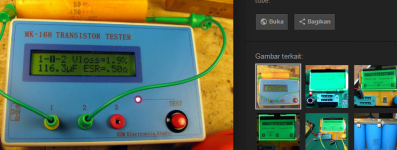
They provide tan alpha. But this is an ideal spec for new product. In a situation where you need to check if an old cap is good or not, or your area is flooded with fake parts, you cannot rely on the spec sheet. Nowadays, there are many cheap uC-based tool which have more functionality than the old expensive multi-meter and LCR meter. See pic.Where can I find information about Vloss from the manufacturers?
Because when you know all the correlation between specs and sound, you don't need ears anymore. All we can hear is measurable. Don't be like pure subjectivists who think that measurements have no value, and don't be like objectivists who think that these people with sensitive hearing do not have value to share. We need both to know the correlation between numbers and sound quality.Yes your right again Anatech. Don’t know why many are caught up with specs, speed etc.
That's because more than 90% schottky have a very good combination of low Ir and low Vf.but theres something about Schokty diodes that draws me in.
You can filter any spikes caused by speed diodes with high Vf with resistor and 'high' quality capacitor, but a resistance in power supply line has its own issue.I use a resistor between the rectifier and the first capacitor as well. For a very good reason.
It's spec is similar to high speed diode (too high Vf). Some people like high speed diode some don't, so you can't blame your taste. High speed diodes can provide detailed sound, but the spikes provide harsh sound. As this harsh sound can easily be heard by people with sensitive ears, you can see that their audio preference in general is less 'transparency' but ear-friendly sound. Sumotan has a diode with a very rare combination of low Ir and Vf. Your CSD has max Vf of 1.8V, Sumotan's bridge has max Vf of 0.9V (other parameters are acceptable). My standard is actually 0.5V without sacrificing the other parameters (expensive, but yes, you can find it).I've got some Cree CSD 010160 Sil Carbide diodes here that I couldn't get a good result - might have missed something I guess
One reason (among other objective reasons) why good audio parts are expensive is because there are people who know that they are good (niche market demand).But from a cost perspective, you might think they are the best diodes around (they do have a rather low forward voltage drop).
I think there will be no issue with resistor type. The benefit is you get an RC filtering and because capacitance is huge you don't need high resistance to get to proper RC value. I don't like the sound of any series R in the power supply. My mosfet (in the active power supply) has an Rdson less than 0.05 Ohm.Here again is another can of worms wrong type will affect the sound. Tried some Dale heat sink wire wounds before & they're not to my liking.
Attachments
Last edited by a moderator:
You remind me of DF96 Johnego. lol Lets put it this way me no electrical background & not as smart as many who are here who can design etc. What I’ve got is a pair is sensitive trainned ears & the compulsion to test & experiment. So what I can hear many a times correlates with what other experience when measured but at the same time I take a different approach to voicing of my equipment. Regardless at the end of the day it’s all about how the system will sound. Btw designers who are good at what they do does not necessarily be able to design a good sounding set up even if they measure perfectly.
Hi all,
There could be so much to reply to, yet I have to "do" something today - so just briefly:
@anatech:
.. and is made by Digilent. There's a link to it here:
@sumotan: Yes, I am fascinated by ESLs or in general planar speakers. Don't yet have any myself but hope soon to have at least an ESL headphone.
@Max Headroom:
@johnego:
Have a good day, All
Jesper
There could be so much to reply to, yet I have to "do" something today - so just briefly:
@anatech:
Hi Chris - it is Analog DiscoveryHi gentlevoice, What is an "Agilent Discovery"? Do you have a model number for it? -Chris
.. and is made by Digilent. There's a link to it here:
@sumotan: Yes, I am fascinated by ESLs or in general planar speakers. Don't yet have any myself but hope soon to have at least an ESL headphone.
@Max Headroom:
Ok, thanks for the recommendation ... will just considerOk IME Lead free solders have a range of critical temperatures and usage of liquid flux is critical. My point/advice is getting Lead out of the overall equation is the very first thing to do. Dan.
@johnego:
Hmmm ... I am not quite sure what you mean but will see if an understanding comes along. Thanks for explaining, though'Vloss' I'm talking about here is the instantaneous voltage loss after the load pulse, and the applied voltage is of course much smaller.
Have a good day, All
Jesper
Last edited by a moderator:
@Monte McGuire: Some days ago I remember asking you if you could outline the setup you use for measuring capacitor distortion (a schematic, if possible, would be helpful). Not to be insisting about this
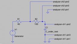
Sorry for the delay - work gets in the way! Attached is a crude drawing of the setup. I’m not familiar with your analyzer and I can’t remember what Cyril Bateman was using, but I’m using an Audio Precision APx-555, which has an extremely low distortion floor, so this may be a reason why my numbers are lower. Also, I'm measuring harmonic spurs directly from 64 averages of a 512K point 192kHz FFT of the analyzer residual, and not THD+N, which would include a lot of noise, and not distinguish between noise and actual distortion, or identify which harmonics are present. In these tests, the noise of the analyzer seems to mask the residual distortion of the generator or analyzer, so there’s no uncertainty from that potential problem.
The 512K point FFT helps to push the analyzer noise floor down, since the analyzer residual (and DUT) noise gets sliced up into many smaller pieces each with less energy. The distortion spurs do not get reduced in level by the wide FFT, since they're pure tones, not random noise signals, so the wide FFT significantly decreases the noise floor level. Still, I can’t see the generator’s residual distortion in these measurements, and maybe that’s a limitation of this setup - a low noise preamp on the DUT could possibly reduce that noise, but for my purposes, it works well enough.
The connection is a single ended drive from the APx high resolution generator set to 40Ω output Z to the 100Ω probe resistor and the cap under test, all in series to ground. I’m reading the voltage across the 100Ω probe resistor and the cap under test using a balanced XLR connection to analyzer channels 1 and 2 of the APx. In this way, I can calculate the impedance of the cap easily, by dividing the DUT voltage over the 100Ω voltage, and scaling the results by 100Ω. Since the probe cabling is the same for both the 100Ω and DUT, you can get HF impedance measurements that are fairly accurate - the probe cable stray impedance divides out.
I originally misspoke and used dBc as the units. From the above, you can see that my data is actually the voltage across the DUT, not a true dBc measurement. So, my 'crud floor' is around -165dBV across the DUT when a 470µF cap is driven with the test signal and probe. The highest drive signal is +15dBV, but to decode that into the current through the DUT, you need to look at the data for the voltage across the 100Ω resistor and convert it to a current.
So, here are some re-stated figures from various caps I tested at 22V DC bias with 2kHz drive, just to keep it all straight. The drive level listed is the current measured through the 100Ω probe resistor, just for accuracy:
Panasonic EEU-FR1V471 with 46.65mA drive: -150.3dBV of 2nd harmonic, -128.3dBV of 3rd harmonic.
Panasonic EEU-FM1V471 with 46.65mA drive: -153.1dBV of 2nd harmonic and -135.2dBV of 3rd harmonic.
UCC EKZM350ELL471MJ16S with 46.71mA drive: -154.6dBV of 2nd harmonic and -143.2dBV of 3rd harmonic.
UCC EKZN350ELL471MJ20S with 46.65mA drive: -155.2dBV of 2nd harmonic and -146.1dBV of 3rd harmonic.
Nichicon VX 470µF 35V with 46.70mA drive: -159.3dBV of 2nd harmonic and -146.0dBV of 3rd harmonic.
Nichicon UFG1V471MHM1TO with 46.70mA drive: -151.8dBV of 2nd harmonic and no measurable 3rd harmonic (below system noise floor)
Elna RFS-35V471MJ7_5 with 46.71mA drive: -162.1dBV of 2nd harmonic and no measurable 3rd harmonic (below system noise floor)
Nichicon UHW1V561MPD with 46.72mA drive: -157.9dBV of 2nd harmonic and -145.1dBV of 3rd harmonic.
I hope this clarifies things a bit. The use of 470µF and 22V bias was because of the circuit I’m using these caps with, and the drive levels of ~45mA correspond to a very heavy signal induced ripple current, again from what I could expect worst case from my circuit. These caps were examined as power supply bypass caps, and while there are differences, these distortion levels are extremely low. In my circuit, a regulator follows the caps, so the actual levels are largely academic, and extremely low. Still, these measurements are reliable, and may help to identify their relative performance. Further, their absolute performance is probably worse with a complex music signal, and not a pure sine wave, so while these distortion numbers are very very low, I think they can still be useful to identify relative ‘cleanliness’.
Attachments
Last edited:
One thing I forgot to describe is that my impedance probe includes a composite of 48 paralleled 10µF 200V metallized polypropylene caps to couple the generator to the 100Ω probe resistor, in order to shield the generator from the DC bias used in these tests. These caps are pretty high quality, designed for speaker crossovers, and each is around 0.75” x 2” size. Each cap was also screened for distortion using the APx, and only 2 or 3 were excluded from the group of 48 due to slightly questionable distortion levels, presumably from termination problems (schoopage failures) inside of the cap. In practice, the composite 480µF polypropylene cap seems to behave well, and I cannot measure its distortion in use.
Sorry for the omission, but yes, it is important to shield the DC bias voltage from the APx generator output, at least to insure that the generator circuit is not biased out of its linear range, and also to prevent any damage to the generator circuitry.
Sorry for the omission, but yes, it is important to shield the DC bias voltage from the APx generator output, at least to insure that the generator circuit is not biased out of its linear range, and also to prevent any damage to the generator circuitry.
Where can I find information about Vloss from the manufacturers?
I don't know why my post, answer to gazzagazza is missing, but the picture attached to that missing post is attached to the next post (May be because I edited the last post while there is newer post).The manufacturers give you the 'tan alpha' parameter, as an indication of good new capacitor. For old caps, or if we aren't sure if the cap is original, fake or semi-original, then we cannot rely on datasheet. Simple measurement that correlate with good cap for supply decoupling is the Vloss, as can be seen from the picture, where an ESR meter measures the Vloss as 1.6% which very bad.@johnego:
Hmmm ... I am not quite sure what you mean but will see if an understanding comes along. Thanks for explaining, though
Whoa, I didn't know if the Nichicon VX measures that good, almost as good as the Silmic! I like the sound of the Nichicon VX such that I pulled out many of them from Sony amplifiers (they are too good for STK chip amplifiers), to make a power bank for my amp.Nichicon VX 470µF 35V with 46.70mA drive: -159.3dBV of 2nd harmonic and -146.0dBV of 3rd harmonic.
...
Elna RFS-35V471MJ7_5 with 46.71mA drive: -162.1dBV of 2nd harmonic and no measurable 3rd harmonic (below system noise floor)
Attachments

Last edited by a moderator:
Anatech, do you use regular 1N4004 or similar rectifier? What resistor value and capacitor type do you use? Would you show a simple example of your configuration?Hi sumotan,
I use a resistor between the rectifier and the first capacitor as well. For a very good reason.
Sumotan, thanks for the picture?
Last edited by a moderator:
Gonna check my drawers, but for sure I have the following:Btw AE50, what is this SiC & LL Sikorel are you speaking off ? Not sure James all that I can say is this BD that Im using is very smooth sounding. Someone also mentioned Silicon Carbide Schokty diodes sound very very good but I’ve yet to try.
-Siemens Sikorel (axial) 2200uF/16V
-Epcos Sikorel (axial) 680uF/40V
-Epcos LL (radial) 2200uF/40V
-Siemens LL (rad, snap in) - can't remember, 6800uF probably at 40V or 63V
-Siemens orange NOS, never used, reformed, measure good (470uF/ 63V)
-Siemens black (no LL or Sikorel, used, screw ends (2200uF, 63V)
The others are mostly higher voltage.
Once I tried to replace a favorite vacuum rectifier (AZ11) with a pair of 1N4007 and equivalent resistors together to equal the voltage drop. The result was a subjectively horrible flat soundstage and a huge microdynamics killer. Still not sure behind the scientific reason of this. One my favorite tube rectifiers are mercury vapor based. They give a specific "punch" and "slam" and a sense of dominance, but don't have the finesse of some fancy non-gas vacuum tube rectifiers. For low voltage applications, I'm enjoying Schottky's at the moment. Not sure why, but they preserve microdynamics a lot and they seem to lack that harsness and smearing I've heard with all PN diodes I tried. Could it be their leakage reverse current that somehow reduces the ringing during switch off? What if we artificially add a high value resistor in parallel to a PN diode and listen and measure?exactly that job, and they do it the best. They are only cheap because so many are used by industry. The expensive rectifiers aren't superior. They are designed for a different purpose and are made in much smaller quantities. That is why they are expensive. Plus they are designed for a different set of operating conditions. Try looking up the actual manufacturer data sheets and have a read. The manufacturer will tell you what job they were designed to do.
Last edited by a moderator:
Guys would like to share some findings. This was brought to my attention from fellow member Eldam, I believe Peter Daniels was the first person who mentioned this but I wasn’t paying attention to it then. Anyway decided to put it to test & true enough nite & day difference.
Bipolar capacitors regardless any brand, always solder the positive leg of the cap to ground.
Why so much diff in Sq, I suspect electrons working more efficiently this way. Proof of the pudding test it yourself pls
Bipolar capacitors regardless any brand, always solder the positive leg of the cap to ground.
Why so much diff in Sq, I suspect electrons working more efficiently this way. Proof of the pudding test it yourself pls
- Home
- Design & Build
- Parts
- Best electrolytic capacitors