OK, so if my understanding is right, then the usefulness of an Audio Interface for your purpose is determined by the maximum output level? Agreed, the UMC202HD with just 0.98V RMS output level @ 0 dBFs is less than the 1.26 V from the UCA and is too low for many applications. And if you want to reduce the THD of the UMC202HD to a more useful level, you'll even have to set the output level a few dBFs lower and reduce the level to, say, 0.8V. But a low output level is easily fixed by an external, single Op-Amp amplifier with 5X amplification and powered by two 9V batteries. Then you'll get an even more usable output range, and you'll be able to test the NAD amp up to its specified input level of 2V or more.
From the NAD amp FFT plot and the UCA loop-back FFT plot you shared, I fail to see how the UCA can be a useful instrument to measure the NAD THD performance, as the THDs are in the same order of magnitude (NAD @ 0.004%, UCA loop-back 0.0031%). You could try the REW harmonic cancellation feature to polish up the fidelity of your measurements, though. Or you could add a notch filter to the input as described in this thread to get rid of the fundamental frequency in the FFT and prevent distortion introduced by the sound card. On top of this, I would consider the SNR of a little over 70 dB, that I calculated from the loop-back plot to be far from adequate.
A comparison between the UCA222, UMC202HD and a laptop soundcard was made here on Audio Science Review: https://www.audiosciencereview.com/...eview-and-measurements-behringer-uca222.2036/
Conclusion: If you're on a budget, you're probably better off using the laptop soundcard rather than a UCA222. Except maybe if the max output level of the laptop soundcard is too low.
Cheers, Jan
You've assumed I am wanting to measure super low levels of distortion.OK, so if my understanding is right, then the usefulness of an Audio Interface for your purpose is determined by the maximum output level? Agreed, the UMC202HD with just 0.98V RMS output level @ 0 dBFs is less than the 1.26 V from the UCA and is too low for many applications. And if you want to reduce the THD of the UMC202HD to a more useful level, you'll even have to set the output level a few dBFs lower and reduce the level to, say, 0.8V. But a low output level is easily fixed by an external, single Op-Amp amplifier with 5X amplification and powered by two 9V batteries. Then you'll get an even more usable output range, and you'll be able to test the NAD amp up to its specified input level of 2V or more.
From the NAD amp FFT plot and the UCA loop-back FFT plot you shared, I fail to see how the UCA can be a useful instrument to measure the NAD THD performance, as the THDs are in the same order of magnitude (NAD @ 0.004%, UCA loop-back 0.0031%). You could try the REW harmonic cancellation feature to polish up the fidelity of your measurements, though. Or you could add a notch filter to the input as described in this thread to get rid of the fundamental frequency in the FFT and prevent distortion introduced by the sound card. On top of this, I would consider the SNR of a little over 70 dB, that I calculated from the loop-back plot to be far from adequate.
A comparison between the UCA222, UMC202HD and a laptop soundcard was made here on Audio Science Review: https://www.audiosciencereview.com/...eview-and-measurements-behringer-uca222.2036/
Conclusion: If you're on a budget, you're probably better off using the laptop soundcard rather than a UCA222. Except maybe if the max output level of the laptop soundcard is too low.
Cheers, Jan
I'm not. I use REW and the UCA222 to check what I've made or bought or modified to ensure the results are decent.
I'm a pragmatist and yes, maybe the HP laptop's sound card could give similar results but for £25 it's a no-brainer using the Behringer.
I'll see whether the iRig HD2 performs better in a few days.
I'm not denigrating your work, just giving my experience of unmodified UMC202HD, a Presonus Audio Box One and a Chinese copy, where I spent hours adjusting the controls and not getting as good as result as the UCA222.
There seems to be a gap in the market for an audio interface offering 24bit 96Khz+ fs with a LP filter appropriate for the sampling rate. All the current ones cut off at about 20-22kHz regardless.
"There seems to be a gap in the market for an audio interface offering 24bit 96Khz+ fs with a LP filter appropriate for the sampling rate. All the current ones cut off at about 20-22kHz regardless."
There is a good chance that you are wrong. I experienced similar limitations - until I discovered that pulseaudio on my linux did resampling which results in a 20kHz brick wall bandwidth. After disabling this I could measure linearly up to 80kHz at 192kHz sampling rate with my old EMU interfaces. I assume a similar setting in windows machines.
Keep in mind that PC default settings aim at the consumer market, these are not intended as lab equipment.
Hi,
first of all I wish you a happy new year.
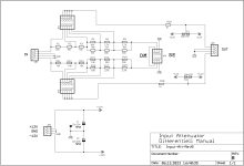
I was pretty busy doing some input attenuator boards both single ended and differentiell, manuall (jumper) or with relay.
Here are some pictures.

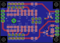
This is the manuell version. Two times single ended (stereo) or one times differential.

This is the single ended version using relay to switch. Can be controlled by a rotary switch or a controller (Arduino, ESP etc)

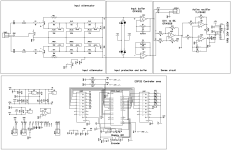
Now the differential one with relay.

This is how the SE relay attenuator may be connected to my dual fliege notch. The voltage regulator board is under the notch.
 Finally the differential version. From left the diff attenuator, fully differential amp, dual notch filter. Above the amp is the voltage regulator.
Put it in a box with some switches and connectors and you get a nice instrument.
If you like to get some blank boards, just ask.
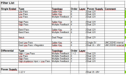
Attached the schematics and layouts of the attenuator and a list of my filter boards.
If you have questions, just ask.
Alfred
first of all I wish you a happy new year.
I was pretty busy doing some input attenuator boards both single ended and differentiell, manuall (jumper) or with relay.
Here are some pictures.
This is the manuell version. Two times single ended (stereo) or one times differential.
This is the single ended version using relay to switch. Can be controlled by a rotary switch or a controller (Arduino, ESP etc)
Now the differential one with relay.
This is how the SE relay attenuator may be connected to my dual fliege notch. The voltage regulator board is under the notch.
Put it in a box with some switches and connectors and you get a nice instrument.
If you like to get some blank boards, just ask.
Attached the schematics and layouts of the attenuator and a list of my filter boards.
If you have questions, just ask.
Alfred
Attachments
-
Input-Att-Rel1-RevA.sch470.4 KB · Views: 30
-
Input-Att-Rel1-RevA.brd106.1 KB · Views: 35
-
 Input-Att-RevB-Sch.png8.8 KB · Views: 45
 -
 Input-Att-RevB-lay.png17.6 KB · Views: 46
 -
Input-Att-Rel-Diff-RevA.sch519.5 KB · Views: 32
-
Input-Att-Rel-Diff-RevA.brd150.4 KB · Views: 31
-
 Filter-List.PNG12.1 KB · Views: 41
It is not unusual that software assumes you need full duplex device. When I tried to have a look at the ultrasonic images of my NOS DAC I had to set my soundcard at 192kHz and feed the DAC with 44,1kHz from Audacity. As output device in REW, the DAC was following the soundcard settings and upsampling."There seems to be a gap in the market for an audio interface offering 24bit 96Khz+ fs with a LP filter appropriate for the sampling rate. All the current ones cut off at about 20-22kHz regardless."
There is a good chance that you are wrong. I experienced similar limitations - until I discovered that pulseaudio on my linux did resampling which results in a 20kHz brick wall bandwidth. After disabling this I could measure linearly up to 80kHz at 192kHz sampling rate with my old EMU interfaces. I assume a similar setting in windows machines.
Keep in mind that PC default settings aim at the consumer market, these are not intended as lab equipment.
MS WindowsI assume a similar setting in windows machines.
If using a single PC with a single soundcard serving as both ADC and DAC, within a single software program, we can set both ADC and DAC to the same sample rate only.
When accesing the soundcard through two software programs, ADC and DAC of the soundcard can be set to different sampling rates.
Java drivers work up to 16bit depth. ASIO and WASAPI go higher, up to the capabilities of the soundcard.
As Windows can play tricks, it is necessary to verify (or enforce) the bit depth and sample rate that each of the ADC and DAC are set.
How? Some clicks and slashes:
Start/Settings/Devices/Sound Settings/Sound Control Panel
then:
for DAC:
/Playback/(click on device)/Properties/Advanced/(click on B.D. and S.R. combination you want)/Apply/OK
for ADC:
/Record/(click on device)/Properties/Advanced/(click on B.D. and S.R. combination you want)/Apply/OK
George
MS Windows
If using a single PC with a single soundcard serving as both ADC and DAC, within a single software program, we can set both ADC and DAC to the same sample rate only.
When accesing the soundcard through two software programs, ADC and DAC of the soundcard can be set to different sampling rates.
Java drivers work up to 16bit depth. ASIO and WASAPI go higher, up to the capabilities of the soundcard.
As Windows can play tricks, it is necessary to verify (or enforce) the bit depth and sample rate that each of the ADC and DAC are set.
How? Some clicks and slashes:
Start/Settings/Devices/Sound Settings/Sound Control Panel
then:
for DAC:
/Playback/(click on device)/Properties/Advanced/(click on B.D. and S.R. combination you want)/Apply/OK
for ADC:
/Record/(click on device)/Properties/Advanced/(click on B.D. and S.R. combination you want)/Apply/OK
George
IK MULTIMEDIA iRIG HD2 MONO 24bit 96kHz INTERFACE.
Tested this today and found:-
It's very sensitive on max gain - about 90mv for guitar pickups.
It has a thumbwheel input level control with a wide range of adjustment - on minimum iit s too low for the max loopback output
The multicolour led needs to stay in the green when sampling.
It supports upto 96K sampling so I set the REW's range to 48K.
The input and output are 1/4" TS jacks, easily converted to RCA with adaptors.
REW uses the Java driver.
The screenshots are of loopback tests.
Hi all...
I'm doing a second version of my SuperRanger motherboard, and as I changed the "input" protection for the buffer opamp to the same as the input protection @MagicBus did on his balanced board for the Behringer.
Q: Will it be correct to not load R7/R8, or maybe use a lowish say 50ohm instead ?
My input protection circuit:
Note I also attached the complete circuit here.

@MagicBus board:

I'm doing a second version of my SuperRanger motherboard, and as I changed the "input" protection for the buffer opamp to the same as the input protection @MagicBus did on his balanced board for the Behringer.
Q: Will it be correct to not load R7/R8, or maybe use a lowish say 50ohm instead ?
My input protection circuit:
Note I also attached the complete circuit here.
@MagicBus board:
Attachments
Hi Jesper,
I'm not the most knowledgeable around but usually the RC network at the feedback loop is used to kill possible oscillation. Values depend on the frequency of interest. In one of my early PCB I had provided pads for SMD parts so to keep traces short if I just wanted to bridge the resistor and since this was the case, those parts were omitted latter in the design.
I'm not the most knowledgeable around but usually the RC network at the feedback loop is used to kill possible oscillation. Values depend on the frequency of interest. In one of my early PCB I had provided pads for SMD parts so to keep traces short if I just wanted to bridge the resistor and since this was the case, those parts were omitted latter in the design.
@MagicBus Thank's...
I also read something like that, and it's also working as expected in the balanced Behringer board.
Reason I had them 3k at my first motherboard/attenuatorboard is that the input protection had an resistance of around 3k, but as there are none "resistance" on this one, I will try to just use an "0" ohm thinfilm SMD resistor, and not load the capacitorpad with anything for a start.
I'm testing my output targetcard, which I prototyped for the last many many months (really enjoying it i must confess)
It's sittting in my SuperRanger V1.0 box now for some testing.
EDIT : I was allowed to use AMB's circuit for this outputcard (modified to have relay adjustable gain's)
https://www.amb.org/audio/alpha24/
Hi...
Yes, I will use a bulb at the RPL / RPR (ResistorProtectionLeft, ResistorProtectionRight or bulb) @ -0dB
Let's see how it goes.
I could also place it at F1/F1, but the idea is that when voltage is settled or under control, the signal can go directly into the buffer without any protection at -0dB, just as my working SuperRanger V1 is working.
As soon as attenuation is engaged at (K5) -6dB ---> -42dB the attenuator resistors will be part of the diode protection circuit.
I think it would work")
Jesper.

Yes, I will use a bulb at the RPL / RPR (ResistorProtectionLeft, ResistorProtectionRight or bulb) @ -0dB
Let's see how it goes.
I could also place it at F1/F1, but the idea is that when voltage is settled or under control, the signal can go directly into the buffer without any protection at -0dB, just as my working SuperRanger V1 is working.
As soon as attenuation is engaged at (K5) -6dB ---> -42dB the attenuator resistors will be part of the diode protection circuit.
I think it would work
Jesper.
Hi Jesper,
Inputs should be shorted, else you would be measuring the Johnson noise of the 20k resistors to ground. FYI, when noise level of microphone preamps are measured, it is quite common to use a 150 Ohm resistor, representing a typical mic impedance. But we're talking about a measuring instrument here and then you'll want to know the noise floor of the instrument itself, because the source impedance is unknown.
Jan
Having a little accident with my little oledscreen, so please don't mind the big blue one on the pictures.
- A new cheapish (8Eur 1.3" oled) is on the way with mailman now
I was for sure excited when trying the autoranger part of the (modified AMB alpha24) piggyback board.
Fortunately it behaved much better that I could have possible hoped for.
The autoranging part / outputcard is just converting the input signal to an userchangeable targetlevel. Which I allready explained here.
So what I was thrilled to see, was how much distortion and noise the output card would add, and if it would work proberly also.
Well.... Pictures below:
I'm so satisfied with the result, but there are still a long way doing the code and calibrating the in/out number's, but it's fun to do.
Noisefloor with shorted input's through the two lightbulb's
(There aren't really any change compared to sending the input through the MELF attenuator resistors) :

To have something to compare with, sending an 1kHz (Victors osc.) directly into the Behringer:

Now 1kHz ---> SuperRanger (gain is automatically set at 1.3):

At -6dB:

And for now at -12dB:

There aren't much difference THD wise, how much gain the outputcard set's (ranging from x1.1 to x1.9)

Jesper.
- A new cheapish (8Eur 1.3" oled) is on the way with mailman now
I was for sure excited when trying the autoranger part of the (modified AMB alpha24) piggyback board.
Fortunately it behaved much better that I could have possible hoped for.
The autoranging part / outputcard is just converting the input signal to an userchangeable targetlevel. Which I allready explained here.
So what I was thrilled to see, was how much distortion and noise the output card would add, and if it would work proberly also.
Well.... Pictures below:
I'm so satisfied with the result, but there are still a long way doing the code and calibrating the in/out number's, but it's fun to do.
Noisefloor with shorted input's through the two lightbulb's
(There aren't really any change compared to sending the input through the MELF attenuator resistors) :
To have something to compare with, sending an 1kHz (Victors osc.) directly into the Behringer:
Now 1kHz ---> SuperRanger (gain is automatically set at 1.3):
At -6dB:
And for now at -12dB:
There aren't much difference THD wise, how much gain the outputcard set's (ranging from x1.1 to x1.9)
Jesper.
- Home
- Design & Build
- Equipment & Tools
- Behringer UMC 202HD for measurements