Hi TT,ttan98 said:The problem is overloading the 6 output stages. The o/p from CD player to high for the o/p stages. It sometimes overload the A & B inputs.
What I did was to attentuate A&B by 6db and o/p stages 1 to 6 by 6db. That fixes the problem.
the 6db of attenuation will be appropriate for analogue inputs to the A&B channels. I found that my RCA connected CD player (unbalanced) required -8db at the input to avoid clipping.
But, with a digital input to channelA, one should not need to apply any input attenuation with the low level (500mVpp) that comes from the Spdif.
With both types of input (digital & analogue) the following stages must be set to avoid any clipping in the analogue output.
oettle said:Hi ttan96,
There can't be any overloading caused by the digital input!!!
Might be you are amplifying the signal within the DCX? The sum of your input gain, EQs and output gain must never be higher than 0dB otherwise you loose resolution.
Frank
Frank is right. The digital input can max be 'all ones' in the data word. That will light up the input LEDs if you use digital input. If you have set the DCX flat, (no lift in any equalizers etc) a digital max signal (all ones, but it has nothing to do with the actual voltage levels at the digital input of course) cannot clip the outputs.
Jan Didden
My mods done
After I did my analog mods to DCX I was itching to do some more. So digital portion was ready to be worked on. I have been waiting and thinking what to do for a long time.
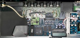
My set up was: Sony CD player XA20ES which is very good transport but it is supplied only with optical TOSLINK out. - SRC2496 which I used to input TOSLINK and to output AES/EBU out to DCX2496. That alone is not ideal set up and is great jitter generator with all cabling. Than from DCX I chopped all analog stuff after AK4393 DACs and sent it straight to 6 Lundahl transformers - one for each ballanced channel. After them I use digitaly controled relay attenuator, than XBOSOZ preamps and than amps.
My analog mod was wiring connected to X13 connector on the DCX analogue board and was messy. So the first thing to do was to sort that out. But first I wanted to mod my CD player so I could avoid SRC and send S/PDIF signal straight to DCX.
So I conntacted Scientific Conversion here in the Bay area that makes highly regarded digital transformers. Jon Paul who is main designer and owner is very cool guy who has helped me design new output for Sony. I installed new tranceiver 485 chip with Scientific's top of the line digital transformer SC937-02 and with termination for 75 ohms. Here is the link for you for that transformer:
http://scientificonversion.com/catalog.html
Thank you Jon very much!
After that I turned to DCX. I used Jan Diden's passive board to make my analogue connections cleaner. Jans board deals only with outputs and additional RS232 sub board is there for the PC control that I use all the time. That was great for me since it omits all of the inputs that I do not use at all but digital in only. I do use occationally C input for auto delay calibration, but I have second DCX that will be great just for that purpose when needed.
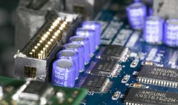
So I proceeded with that mod, did all the flat cables and volia - that was done. Next I got Neutrik RCA connector for my 75 ohm coax S/PDIF input, and smallest Monster digital cable to rout the signal. I used empty space on Jan's board to have cable secured and wired to 1 and 2 connector on X13.
Next in line was Transformer and AES/EBU 110ohm termination resistor replacement. In the place of original transformer which was through hole, I placed Scientific Converesion's small beauty which is SMD, but almost perfectly fits in the place of original transformer. That little guy, unlike original one is shielded and it provides shielding connector. I replaced 110 ohm SMD resistor with 75 ohm that is located on the bottom side of the DSP board. Scientific has through hole transformers, but Jon was clear that this small guy is just the best performer overall. So, that was done.
Lets have some pictures than I will continue.
After I did my analog mods to DCX I was itching to do some more. So digital portion was ready to be worked on. I have been waiting and thinking what to do for a long time.
My set up was: Sony CD player XA20ES which is very good transport but it is supplied only with optical TOSLINK out. - SRC2496 which I used to input TOSLINK and to output AES/EBU out to DCX2496. That alone is not ideal set up and is great jitter generator with all cabling. Than from DCX I chopped all analog stuff after AK4393 DACs and sent it straight to 6 Lundahl transformers - one for each ballanced channel. After them I use digitaly controled relay attenuator, than XBOSOZ preamps and than amps.
My analog mod was wiring connected to X13 connector on the DCX analogue board and was messy. So the first thing to do was to sort that out. But first I wanted to mod my CD player so I could avoid SRC and send S/PDIF signal straight to DCX.
So I conntacted Scientific Conversion here in the Bay area that makes highly regarded digital transformers. Jon Paul who is main designer and owner is very cool guy who has helped me design new output for Sony. I installed new tranceiver 485 chip with Scientific's top of the line digital transformer SC937-02 and with termination for 75 ohms. Here is the link for you for that transformer:
http://scientificonversion.com/catalog.html
Thank you Jon very much!
After that I turned to DCX. I used Jan Diden's passive board to make my analogue connections cleaner. Jans board deals only with outputs and additional RS232 sub board is there for the PC control that I use all the time. That was great for me since it omits all of the inputs that I do not use at all but digital in only. I do use occationally C input for auto delay calibration, but I have second DCX that will be great just for that purpose when needed.
So I proceeded with that mod, did all the flat cables and volia - that was done. Next I got Neutrik RCA connector for my 75 ohm coax S/PDIF input, and smallest Monster digital cable to rout the signal. I used empty space on Jan's board to have cable secured and wired to 1 and 2 connector on X13.
Next in line was Transformer and AES/EBU 110ohm termination resistor replacement. In the place of original transformer which was through hole, I placed Scientific Converesion's small beauty which is SMD, but almost perfectly fits in the place of original transformer. That little guy, unlike original one is shielded and it provides shielding connector. I replaced 110 ohm SMD resistor with 75 ohm that is located on the bottom side of the DSP board. Scientific has through hole transformers, but Jon was clear that this small guy is just the best performer overall. So, that was done.
Lets have some pictures than I will continue.
Attachments
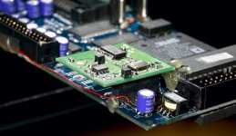
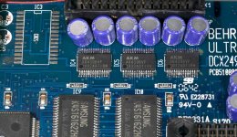
Next on assembly line was replacement of dreaded CS8420 input chip that has all kind of problems. I also wanted to do clock mod as well, I was for a long time thinking what are my choices. Than Frank Oettle came with his great small board that deals with both all at once. That is a small square board in the place of original input chip. Frank's board houses and uses CS8416 receiver chip, highly regarded AD1895 192 kHZ Stereo Asynchronous Sample Rate Converter, each with its own low noise regulator, and on the top of that Ultra Low jitter clock! Board was fine to assemble and it connects through connector to the board. Connector is soldered in the place of CS8420, only on one row, where few small wires needs to be connected from a second row. That was hard! Additionally one wire is needed to bring regulated 9V from power supply. I was also doing power supply replacement from Stephane who made great boards for DEQ2496. Unfortunately that couldn't work for me since Frank's board needed nice stable 9V supply. So I was back to original Behringer power supply.
Here is the picture of Frank's board. Red wire is 9V supply from power supply connector.
Here is the picture of Frank's board. Red wire is 9V supply from power supply connector.
Attachments
Next was listening test to check what it does. I was very curious to hear if all jitter talk is really something that makes sense or I would need to have special ears to hear the improvement.
It is understatement to say that I was blown away. I just couldn't believe that such a difference is possible. I would rate this improvement equal to analogue mod when I removed all opamps and replaced them with Lundahls.
What immediately became noticable was channel separation and imaging. The hole sound unfolded nicely and it had whole another depth. The voices are dead centered and instruments are behind on the sides. Highs are much cleaner and with nice detail. The grain was gone. I was just amazed that such a improvement is possible. I really would like to hear if everyone else who did this mod found the same improvement.
I believe that simplifying digital line, using low jitter transformers, and than Franks board that obviously addresses several issues that existed did it. I am trilled!
Thank you Frank - great board!
I would strongly advise this mod, as long as you are comfortable soldering very small SMD parts. Frank provides assembled board, but you would need to do connector and wires soldering.
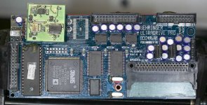
Here is one more shot - DSP board. I replaced all electrolythic caps with OSCONS - there were a lot of them. I also removed AK 5383 AD converters. Since I am not using analog in, there was no reason for them to just seat there and use power.
It is understatement to say that I was blown away. I just couldn't believe that such a difference is possible. I would rate this improvement equal to analogue mod when I removed all opamps and replaced them with Lundahls.
What immediately became noticable was channel separation and imaging. The hole sound unfolded nicely and it had whole another depth. The voices are dead centered and instruments are behind on the sides. Highs are much cleaner and with nice detail. The grain was gone. I was just amazed that such a improvement is possible. I really would like to hear if everyone else who did this mod found the same improvement.
I believe that simplifying digital line, using low jitter transformers, and than Franks board that obviously addresses several issues that existed did it. I am trilled!
Thank you Frank - great board!
I would strongly advise this mod, as long as you are comfortable soldering very small SMD parts. Frank provides assembled board, but you would need to do connector and wires soldering.
Here is one more shot - DSP board. I replaced all electrolythic caps with OSCONS - there were a lot of them. I also removed AK 5383 AD converters. Since I am not using analog in, there was no reason for them to just seat there and use power.
Attachments
Well the last one was to exchange AK4393 DACs for AK4396s. They are newer chips, very well accepted in reviews, lower in power consumption and they are 24 bit 192 kHz capable. This last detail is not too important since the whole DSP board is made for 96 kHz. This chips are the smallest possible. I used hot air gun to take them out and that was not hard. Soldering is something that needs to be done carefully. I do not like hot air gun and solder paste for soldering since it could easily move under chip and be invisible while it short circuiting. I used tiny solder and finest tip I have. Here is the result.
Attachments
I did listening after and yet there is another improvement. Mostly in the highs. They are more detailed and overall nicer, silkier I would say. It is not even near to improvement done by Frank's board, but it is noticable improvement. Together with all other mods I would say it is completely new sound. I am very happy. Everything that I did really made improvement and it was worth the effort.
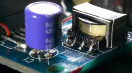
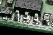
After all this while I was making pictures for you guys, and while I was inside this micro world, I made a really nice macro shot of a small SMD transistor that I like very much. That is bonus shot! It is amazing how references are exchanged with distances. Look how rough surfaces are in this small world.
I hope this walk through my mods inspires someone, but be aware you would need good tools and strong viewing aid for this micro
environment.
Thank you all that helped me come to this point - Jon, Jan, Frank and Stephane!
Attachments
Zen Mod said:nice to know that things are moving in right direction
Sleepless Man ........
Ha, you do not miss anything. I just sent you an email to make you aware, but you are faster...
Talking about sleepless man - I cannot compete with you.
")
AndrewT said:Hi Ar2,
How I wish you lived in the UK.
I would send my dcx2486 for you to update.
Well done.
Can you give some interim sound quality reviews of each stage of the modifications, or did they all get done at one time?
In hindsight, which mods give best value?
Thank you AndrewT,
If you decide to do some mods, I will be happy to help you.
I did more or less work in groups, and I did listen in between, but these groups are as written. I did my analogue conversion long time ago, so Jan's passive board is used only for rerouting in my case. I do not know what is that affects sound improvement so much, but I would think that combination of all did it. I strongly believe in simplification, and loosing SRC from the chain, switching from TOSLINK to coax through the transformers dramatically lowered noise floor and jitter. Than I believe above all Frank's board did the major improvement. I do not know if you guys are aware, but I was reading somewhere that CS8420 is faulty chip, which results in loosing high Fqs. randomly between the channels. I have experienced that without knowing this fact and I was going nuts by trying to figure out that problem.
Realistically Frank's board is the one that addresses several issues and I believe major improvement is there.
Hello AR2,
That is one hell of a complete and radical mod! Well done. Your workmanship on those tiny solderings is first rate. I'm jealous!
I have also Frank's mod on my DCX, but haven't had a chance yet to try it out. I have the power supply dismantled as I am designing my own form-fit replacement linear power supply, but I will put the original supply back in temporarily to test Frank's mod tomorrow or Tuesday. Then I also have comparative performance for when I install my new linear supply.
Jan Didden
Nice modding!
Hi,AR2,what is the number on the smd trafo from Scientific Converesion's?Maybe a good idea to change them in my DEQ to..
Will using a regulator from +15v on Stephanes PSU work?
Hi,AR2,what is the number on the smd trafo from Scientific Converesion's?Maybe a good idea to change them in my DEQ to..
Is the original PSU regulated at 9v?I was also doing power supply replacement from Stephane who made great boards for DEQ2496. Unfortunately that couldn't work for me since Frank's board needed nice stable 9V supply. So I was back to original Behringer power supply.
Will using a regulator from +15v on Stephanes PSU work?
janneman said:Hello AR2,
That is one hell of a complete and radical mod! Well done. Your workmanship on those tiny solderings is first rate. I'm jealous!
I have also Frank's mod on my DCX, but haven't had a chance yet to try it out. I have the power supply dismantled as I am designing my own form-fit replacement linear power supply, but I will put the original supply back in temporarily to test Frank's mod tomorrow or Tuesday. Then I also have comparative performance for when I install my new linear supply.
Jan Didden
Thank you Jan.
I am very curious to see if you find the same regarding that mod. Please let us know.
Ha, you are going through similar thing that I did. I pulled out my power supply, and worked on putting Stephane's - just the digital portion. The transformer 2x7V was nicely placed inside, drilled the holes for new power supply and transformer... When connected I realized that my screen wasn't working. The first taught on my mind was that I screwed something.... than after inspecting everything and checking schematics I realized that screen needs 15V in order to operate. I tried to monkey around and to use original power supply just for that portion to make sure that screen works.
Next thing that happened - my original power supply was smoking and quite honestly I do not know why it decided to quit on me but some things are with the mind of it's own. Than my saga continues - I decided, OK I will order the second transformer for 15V what I wanted to avoid in the first place, and get parts to build 15V supply just for screen to operate. In the meantime I have finished Franks board and wanted to try it... Well, 9V supply is needed to supply two onboard 7805s with proper voltage for regulation down to 5 V. Frank board uses 9V, but Stephane's power supply with 2x7V transformer doesn't give that voltage - it makes 7,7V aprox. what is enough for everything else, but not for what I was up to.
Frank has helped me a lot in discovering all this since I wasn't sure if i have problem with his mod or something else. So I was back to where I started. Decided to pull power supply from my original DCX what I did and everything was back to normal. My second Behringer Power supply - the one that I offered to you in another thread now needs repair. It blows the diode bellow 7815 reg. I changed both reg and diode but it keeps doing the same thing. Oh well...
Ryssen said:Nice modding!
Hi,AR2,what is the number on the smd trafo from Scientific Converesion's?Maybe a good idea to change them in my DEQ to..
Is the original PSU regulated at 9v?
Will using a regulator from +15v on Stephanes PSU work?
If I don't do a mistake, Franck's digital input board already have low noise regulators on the board to fit ADxxx and so. Why do you need to have a regulated 9v?
On the original switched mode psu, the 9v goes to the regulators on the dsp board. It's not used direct as this to drive something.
15v is for analog and op-amps, it's better to let this alone.
You should ask Franck to know what is the minimum input voltage to drive the regulators on its board.
- Home
- Source & Line
- Digital Line Level
- Behringer DCX2496 digital X-over