Hello,
here some fresh ideas for PSU modding. I routed the circuit on a 10x20 mm PCB which is the same size as a TO-220 case and replaced the two 7805 voltage regulators on the DSP-board. D1 is a 6.8V zener and Q2 a SST506 constant current diode. All 10µF caps are X5R 0805 type and the 1n and 10n caps COG/NPO.
This voltage regulator has a PSRR of at least 200dB (10Hz to 10MHz!) and has a low noise output which is much, much better than what I have seen so far.
You can use the same circuit for +/-12V supplies (op-amps), but zener must be increased and a different regulator must be used because the LP3878 supports output voltages only up to 5V. I myself don't need this because I use passive outputs.
Frank
Attachments
ergo said:AR2,
The modding of the XA20ES should not be difficult at all - I have XB930 which is in many ways similar unit and I assume in you player the SPDIF signal comes out from the transport PCB also with a separate 3 wire connector that then goes to DA and analog PCB somewhere near the Optical out socket.
Basicly all you have to do is to use this signal and make a circuit after it to feed the 75 ohm coaxial digital cable. There are many circuits in this forum for that purpose just run a search and pick what seems best to you.
Ergo
Thank you Ergo, very much, but that would be to run coaxial S/PDIF out. I was thinking of having AES/EBU out, for what I assume have to have CS transmitter. That transmitter will output S/PDIF as well, but my interest is AES/EBU. Are you saying that I should use that three wire signal and wire that to the input of CS chip in addition to the clock, power supply...
Hello Jan and Ergo,
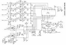
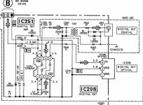
I just have received my schematic for Sony XA20ES. Here is what is inside regarding S/DIF outputs coaxial and optical. Apparently they ddi coax out for UK market and not for US - it seems like it. This schematic might answer question that Jan had, and might help if someone would like to design a mod to make AES/EBU output.
I just have received my schematic for Sony XA20ES. Here is what is inside regarding S/DIF outputs coaxial and optical. Apparently they ddi coax out for UK market and not for US - it seems like it. This schematic might answer question that Jan had, and might help if someone would like to design a mod to make AES/EBU output.
Attachments
I'm just happy the DCX is as modular as it is, it makes input, output and PSU upgrades a breeze. I'm making just about the simplest passive outputs there is; based on Jan's article, but without the mute circuit and onboard DC filter caps. They're 1.9" wide stereo boards, so they'll easily fit in the DCX with room to spare for DC filters. You can even have different output stages for each DAC, if the amps down the line have different requirements.
Anyone interested? They should cost next to nothing if we order some at OurPCB or something.
What I don't understand is why all the mods I've seen so far are using standard ribbon cable between input/output board and DSP board. They're a regular analog signal, for God's sake! And all connectors are standard 10mil spacing, so it's very easy to solder good quality internal wiring to standard 10mil header sockets like these.
Next in line is swapping the AK4393s with DIT4192 S/PDIF transmitters to get full digital out, and swap the AK5393 for a separate input board with an SRC4392 S/PDIF receiver and PCM4220 ADC to get more and better inputs. That's after upgrading PSU and clock, of course.
Attachments
AR2 said:Hello Jan and Ergo,
I just have received my schematic for Sony XA20ES. Here is what is inside regarding S/DIF outputs coaxial and optical. Apparently they ddi coax out for UK market and not for US - it seems like it. This schematic might answer question that Jan had, and might help if someone would like to design a mod to make AES/EBU output.
Thanks AR2 and Ergo, I understand now that optical stuff is really VERY simple! I have an HP 3756A 1-of-10 90MHz switch which I use for digital selection, and I will modify one input for optical toslink in.
Jan Didden
AR2,
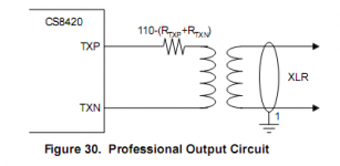
You can make the AES/EBU out for Sony just as well. The only difference is basicly the transformer and passive components to adjust it for 110ohm instead of 75 ohm.
But I would rather mod the input of the DCX to receive the 75 ohm coax as the original digital input layout is more than poor in my opinion. The AES/EBU signal goes from XLR connector to relay, then about 8cm on PCB then through flat cable and connectors, PCB traces again and then finally reaches the CS chip. All this is far cry from proper 110ohm termination to the AES/EBU line....
Ergo
Attachments
I don´t know how you managed to squeeze so much stuff in that smal area..I routed the circuit on a 10x20 mm PCB which is the same size as a TO-220 case and replaced the two 7805 voltage regulators on the DSP-board.
Any pcb leftovers..?
")
Do you know what the PSRR is for the Selectron regulator board?Just to have something to compare with.This voltage regulator has a PSRR of at least 200dB (10Hz to 10MHz!) and has a low noise output which is much, much better than what I have seen so far.
Hi Ryssen,
It's a double sided PCB with all SMD components. It's not a trick.
I'm not aware of the Solectron PSU mod, but I assume they use LM317 or something similar. These standard regulators have an PSRR of about 60dB which gets much worse above 1 kHz (10-20dB at 100kHz-1MHz), that's why there is so much HF noise coming from the switched Behringer PSU. The regulators aren't able to reject this HF noise.
My experience was that with 3 simple 100µH coils between PSU and DSP board you get rid of most of this HF noise and have a similar result as with the PSU mods I have seen so far at a much lower price.
Frank
I don't know for the DCX but on the DEQ, noise come from the DSP board itself too. It back to the PSU from the digital 5v, cross the PSU, and go back to the analog part. This is one of the reason, I've used so many beads in my PSU.
It can be cool to use this kind of "miniVreg" with my PSU too. On the DEQ, analog 5v (for ADC and DAC) is still using a 7805. The LM317 on the DSP board is used to produce digital 2.5v. No need to change this one.
Unless they are SMD parts, put 43 or 45 components on a double side 10x20 pcb is a nice success.
Thanks but I can't make miracles to become true. Including the connector there are only 15 components.
I didn't plan to sell, but obviously there is more interest than I expected. I have 13 spare PCBs left but no components. If you like I could order the missing components for you and deliver complete sets lets say for 20 Euro each. I only need to know how many I should order. Please send me an email - hopefully not too many.
Frank
I'm a so in the start!!! 43 is for the SRC module...
I take one for me. The PCB only if possible. I've spare of smd parts. I just need to source the Q.
The module is interesting because it can handle more than 100mA. Others based on opamp, leds or source current are limited to 80-100mA.
15 parts is also a great challenge. On mine, I only have 6 parts for the same size... It can be put on an heat sink too.
Will send you a mail.
Stephane
The power supply upgrade is an interesting subject, I have been working to find a way to go in my head for a long time. The problem has been that I have not yet found a solution that would be a real step up.
I did change the decpoupling caps around DAC chips for Sanyo Oscon series.
These are the spectrum measurement
pre mod
post mod
The noisefloor did not change much but surprisingly the second and third harmonic relationship did a little.
What is more interesting for me is that the noisefloor shape in DCX is much different than in the Echo Layla24 soundcard I have - the DAC is exact same type in Echo card...
I have not yet figured out where this difference comes from......
************'
The current idea for DAC supply mod is to desolder the 7805 and the cap after that from PCB and wire the new power supply not to the pads of 7805 but to middle decoupling el.cap pads near the DAC-s. That in combination with better power supply would most likely make a very good condition for DAC supplies with a minimal "power supply loop" (assuming of course that regulator is very close to DAC chips).
The problem is a regulator - it should handle 80mA per DAC chip - so 240mA to be on a safe side. There are not very many elegant small solutions for that. Tent Shunt unfortunately does not handle that, otherwise I would have tried it.
Ergo
I did change the decpoupling caps around DAC chips for Sanyo Oscon series.
These are the spectrum measurement
pre mod
An externally hosted image should be here but it was not working when we last tested it.
post mod
An externally hosted image should be here but it was not working when we last tested it.
The noisefloor did not change much but surprisingly the second and third harmonic relationship did a little.
What is more interesting for me is that the noisefloor shape in DCX is much different than in the Echo Layla24 soundcard I have - the DAC is exact same type in Echo card...
An externally hosted image should be here but it was not working when we last tested it.
I have not yet figured out where this difference comes from......
************'
The current idea for DAC supply mod is to desolder the 7805 and the cap after that from PCB and wire the new power supply not to the pads of 7805 but to middle decoupling el.cap pads near the DAC-s. That in combination with better power supply would most likely make a very good condition for DAC supplies with a minimal "power supply loop" (assuming of course that regulator is very close to DAC chips).
The problem is a regulator - it should handle 80mA per DAC chip - so 240mA to be on a safe side. There are not very many elegant small solutions for that. Tent Shunt unfortunately does not handle that, otherwise I would have tried it.
Ergo
Hi Ergo,
Because there is a lot of HF noise coming from the Behringer PSU it would be interesting if there is some improvement with a 100µH coil in the 9V rail.
My Vreg mod is able to handle up to 800mA but then would need some additional cooling. With the typical 180mA for the 3 DACs no cooling is required.
Frank
ergo said:AR2,
You can make the AES/EBU out for Sony just as well. The only difference is basicly the transformer and passive components to adjust it for 110ohm instead of 75 ohm.
But I would rather mod the input of the DCX to receive the 75 ohm coax as the original digital input layout is more than poor in my opinion. The AES/EBU signal goes from XLR connector to relay, then about 8cm on PCB then through flat cable and connectors, PCB traces again and then finally reaches the CS chip. All this is far cry from proper 110ohm termination to the AES/EBU line....
Ergo
Bypassing the PCB path is a very good idea!
And you can do even better and go for the SPDIF setup described in the Cirrus data sheet (for most CD players that output SPDIF only):
An externally hosted image should be here but it was not working when we last tested it.
janneman said:Guys,
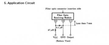
I have been looking into that optical input thing. Am I correct that those Toshiba optical S/PDIF receivers just need a +5V, you plug in the optical cable, and than at their output you have the 'electrical' S/PDIF?? Is that really all there is?
Jan Didden
yes Jan - very easy, and there is TTL/S-PDIF - but I think there's a capacitor and choke (yes, not resisot - see pic) external for digital filter or some such.
the TORX-179 is a nice high speed device, and will go with the 192kHz mod nicely.
Simon
Attachments
Pulse-R said:
yes Jan - very easy, and there is TTL/S-PDIF - but I think there's a capacitor and choke (yes, not resisot - see pic) external for digital filter or some such.
the TORX-179 is a nice high speed device, and will go with the 192kHz mod nicely.
Simon
Thanks. I use an HP high-speed selector unit for digital source selection, and I plan to mod one of the inputs to toslink.
Jan Didden
Hello Ergo,
Very interesting measurements. So far I have no experience with such kind of measurements.
I assume the DCX diagrams are based on the digital input?
If yes the reason for the harmonics could be the CS8420 SRC.
Overall the noise floor seams to be better compared with your soundcard but it would be interesting why it gets worse on the low end. Hopefully the Vreg will improve something.
I don't understand how to measure jitter with such equipment. I assume jitter changes width of the first harmonics, but accuracy of the measurement is based on the accuracy of the ADC of your soundcard which is based on a clock witch jitters (and an ADC with noise floor) itself.
Who has a audio precision?
Can I pick your brain some more. I found a data sheet for the -177, not the -179. It says "pulse width distortion 15nS max". Is that the jitter spec? If so, it doesn't seem too hot.Pulse-R said:
yes Jan - very easy, and there is TTL/S-PDIF - but I think there's a capacitor and choke (yes, not resisot - see pic) external for digital filter or some such.
the TORX-179 is a nice high speed device, and will go with the 192kHz mod nicely.
Simon
Jan Didden
- Home
- Source & Line
- Digital Line Level
- Behringer DCX2496 digital X-over