Great ! You have been busy,NICE JOB
Would you elaborate on the clock and I2s that is next,
Then the power supply,I will only replace the 3.3 and 5.0 I have a Ps to drive the 6 THAT 1512's I am using for outputs,I wish I could hear yours I have installed the 1512's and they make a big difference in sound depth,image and sonics,I'm Happy! and of course no noise,hiss....finally!
What I really need to find out is how to connect the DEQ to the DCX with I2s,
Thanks,
NS
Last edited:
Hi globulegl,
I have 2 cm6132a and xmos a to try using I2s, I did use a usb to spdif to the digi in transformer on board and it works perfectly,I did change the 110r resistor to a 75r and cut those 2 traces on top of the board for old input,Guess it's time to remove 8420 and patch in I2s,
My big plan is to connect the DEQ to DCX using I2s only all inputs will go through the DEQ,I have used aes/spdif and that works,I almost have it!
Thanks for your link!
NS
Hi AndrewT,
I changed that resistor back to 110R it was originally and ran a coax from the DEQ didgi out to the Transformer on the DCX,I used single conductor and gnd ,sound is fine.
Should I run it different?
I would like to run I2s out of the DEQ to CS8420 pads in the DCX to get signal in from a usb to I2s,
or is XLR from unit to unit just as good?
Thanks,
NS
coaxial is not balanced
You need twisted pair, or screened twisted pair for a balanced impedance connection.
Both are 100 to 110ohms characteristic impedance.
That's why it is fitted with XLR feeding into a 110r load. It is the termination for a high frequency 110ohms connection.
Digital is a high frequency and the cable needs appropriate impedance termination at both ends.
I'm not a digital person, but I'm told that for shortish cables, the tolerance to poor impedance matching is better. That may explain the fact it appeared to work at 75ohms.
Last edited:
Hi AndrewT,
Yes you are correct but the wire will be about 6" or so But I will try it with 2 twisted conductors and maybe strip a piece of shielded cable and run the twisted pair through it,
I'll take a look at it with the scope and see how the sig looks,
BTW I have some 200mhz probes,Do I need to add anything to the probe to read digital signals?
Thanks,
NS
Hi AndrewT,
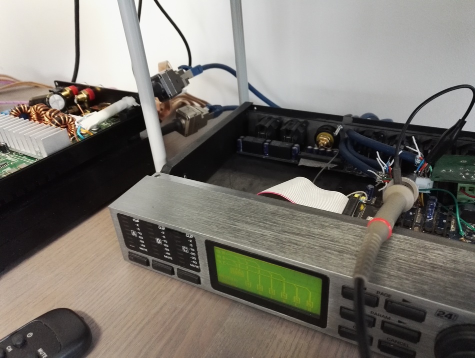
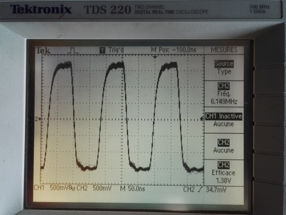
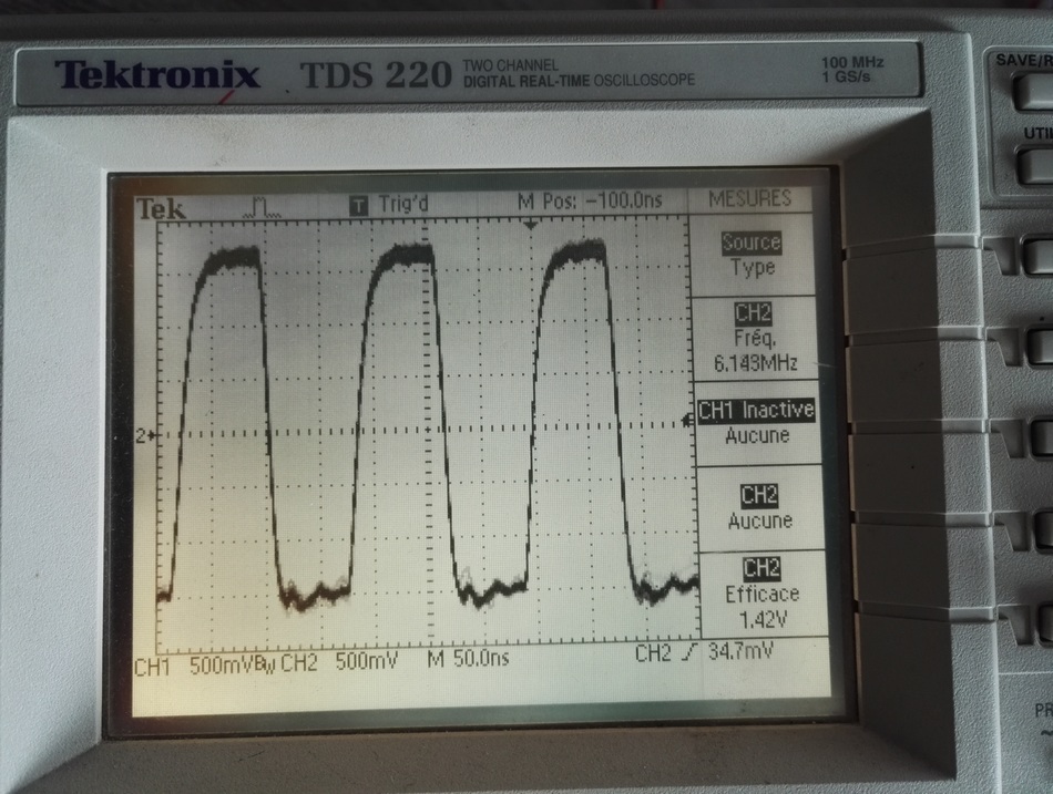
I didn't get a perfect lock but I did see some nasties I didn't like so I removed all the cabling and ran a twisted pair inside a shield and now it looks like a square wave should,so that is done,,,,,
I am going to build a clock board,I would like to supply both boards with one clock divided by2 I have a 24.576 iirc txco I wanted to know about should the wires to the clock pads be shielded?I will mount the board between the boards so 4" would be wire lenghts,
Thanks for your advice,
NS
H.Ott has a lot to say on that.
I wonder if any of his web based articles discuss this?
His book "ELECTROMAGNETIC COMPATIBILITY ENGINEERING" is not cheap.
There is quite a bit on this Forum.
One point I have picked up is that noise into the clock increases jitter
And another is that clock to client is critical to performance. But I don't recall which parameters give good performance, it's not my subject.
Hi globulegl,
Nice waves I can't get a good lock with my scope it was made right before the digital scope hit the market It's about to be replaced but for now I use it.
Did you get those signals from 8420,I haven't removed mine yet ,I did remove and replace all the caps and oh boy it did change the sound totally ,I used oscons everywhere ,I am still listening, as too changing a few of them to something else ,My Deq feeds the DCX now I have a kinda shrillness to my mids and highs almost like it's over driving,so
I would like to get I2s from the DEQ to the DCX but now I have ran a twisted pair from digi out (DEQ) to DCX digi IN and it sounds crisp and clear,then I changed the caps....so maybe I change the caps near the(DCX) 2nd and third 4393's and see if that fixed the shrill ,caps changed did help the bass much more responsive,onward.
I have a Ebay board for USB to I2s to feed the DEQ ,I am currently using USB to spdif/Aes going in the digital input,24/192, The RTA display is much faster and covers the whole spectrum,I am amazed to see alot of 20 to 40 HZ displayed,I guess that the music is uncompressed,I have also noticed that you can tell when tracks are changed and tracks are added in to the mix,I understand why a good recording eng. is needed to produce good music.
Happy Listening!
NS
Here a few pic's
Attachments
-
 102_2189.JPG528.3 KB · Views: 290
 -
 102_2200.JPG544.5 KB · Views: 137
 -
 102_2198.JPG403.8 KB · Views: 135
 -
 102_2196.JPG590.5 KB · Views: 130
 -
 102_2195.JPG385.5 KB · Views: 111
 -
 102_2194.JPG454.9 KB · Views: 119
 -
 102_2193.JPG489.2 KB · Views: 119
 -
 102_2192.JPG321.9 KB · Views: 115
 -
 102_2191.JPG409 KB · Views: 130
 -
 102_2190.JPG538 KB · Views: 154
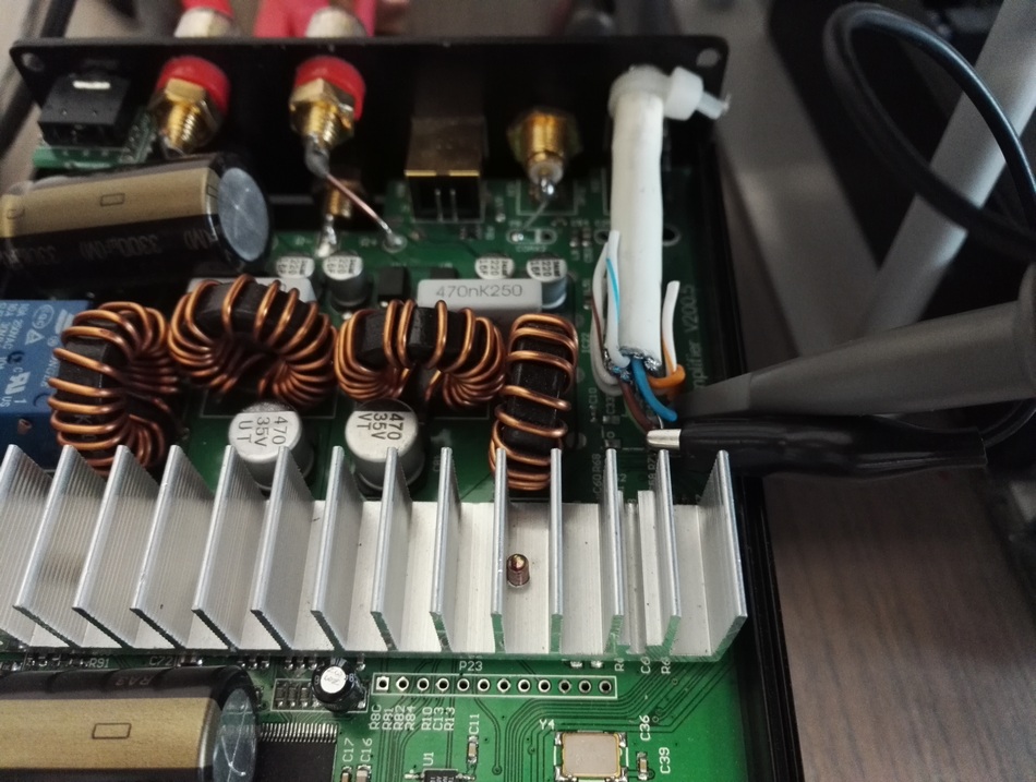
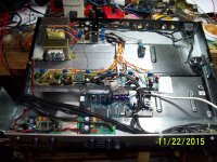
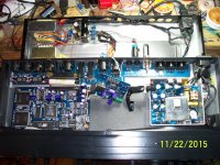
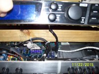
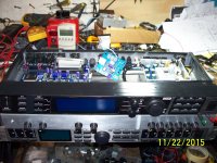
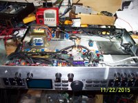
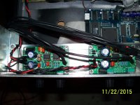
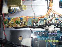
The first 2 pics show the xformer and PS for the 6 THAT 1512's they take the dac out to 1512's and out to the T M W amps on the last pic,The third pic is the sub boards,I run 4way and DCX runs 6 amps and the sub boards run 2 sub amp's to 2 XOc1's subs,
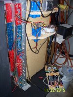
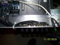
Pic 4 is the volume for each channel T M W on the left is sub volume and Freq control,I tapped off the bass op amps to control the subs,that way the DCX is still controling that feed and I can modify the subs response with the extra controls Vol and freq 20hz to 160Hz on the sub board.Pic 7 is the power supply for the dcx(a new board is being made with separate regs )Pic 8 is the 24/192 board going in the digi in to the deq
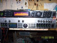
Pic 9 is what it looks like all together, Pic 10 is the water cooler,lol 2X4" The radiator and resavoir are under neeth,,,,so much fun,lol!
NS
Pic 4 is the volume for each channel T M W on the left is sub volume and Freq control,I tapped off the bass op amps to control the subs,that way the DCX is still controling that feed and I can modify the subs response with the extra controls Vol and freq 20hz to 160Hz on the sub board.Pic 7 is the power supply for the dcx(a new board is being made with separate regs )Pic 8 is the 24/192 board going in the digi in to the deq
Pic 9 is what it looks like all together, Pic 10 is the water cooler,lol 2X4" The radiator and resavoir are under neeth,,,,so much fun,lol!
NS
Analog out malfunction
Hi everyone, I'm having trouble with my DCX2496. The first analog out channel started misbehaving recently by presenting frequent and very loud thumps to the speaker. The signal is present and clean between the thumps. They seem to correlate with touching/moving of the jack. A closer inspection revealed that the outputs randomly swing between ~40mV to 14.5VDC on both signal lines simultaneously. As the signal is present in both states and same gain, I figure it must be a lost ground reference somewhere due to mechanically broken resistor or trace.
Now I've poked around with a scope, the first opamp (IC1, see schematic) seems to be OK, it has no DC on pin 7. I haven't much experience debugging this type of virtual balanced circuit. Can anyone give me an advice on which parts are the most likely cause before I go berserk resoldering everything?
Attachments
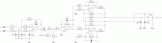
I think you're on the right track. If moving the jack causes the issue it's most likely a broken trace somewhere in the area of U12. Since your outputs swing to the positive direction it's possible the issue is related to the -V input on pin 4 of U12
I suggest to take the board loose from the chassis and take a good visual look. It's kind of a pain with the DCX since many of the components are on the bottom side and you need to remove all the screws on the back.")
Dave.
I suggest to take the board loose from the chassis and take a good visual look. It's kind of a pain with the DCX since many of the components are on the bottom side and you need to remove all the screws on the back.
Dave.
Before you take it apart check the cable that is plugged into the jack with another one,
if it does the same thing then you have a bad solder joint around the jack, I hope you have and electric screw driver,lol.You could resolder the pins from the top side and might get lucky and that fixes it,They use hard solder and it likes heat and some extra flux helps too!
Good luck with it!
NS
if it does the same thing then you have a bad solder joint around the jack, I hope you have and electric screw driver,lol.You could resolder the pins from the top side and might get lucky and that fixes it,They use hard solder and it likes heat and some extra flux helps too!
Good luck with it!
NS
- Home
- Source & Line
- Digital Line Level
- Behringer DCX2496 digital X-over