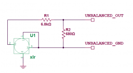
When you ground that pin3 you essentially go from balanced to single ended output. The total difference output signal doesn't change (1/2 signal on pin 2 and 1/2 signal on pin3) but you now measure the total to gnd instead per phase so now it looks like you have the double value. That also explains the increased THD: some of the THD+N is normally cancelled between the phases (that's the reason for balanced in the first place) so you also see a higher THD.
So, in thinking about this a bit more, it seems to me that it might be better not to ground pin 3 if excessive gain is an issue with unbalanced amps, since the increase in THD seems fairly minor. I was a bit confused by your comment though because it sounds like you are suggesting that THD should increase by grounding pin 3, which is not what Charles found (unless I misunderstood).
- Doug
I was using a standard PC soundcard to measure a frequency sweep from My DCX, and one output was varying in level wildly with frequency. Investigation why showed that this was caused by not grounding the unused phase on the XLR output. The lead I had had the signal connected to pin 3 (to suit a BSS Crossover). Given that the output pair of Op-amps can float I think that the idea of not shorting one pin to reduce the output gain is questionable. If the other pin can swing voltage, there is no reference for the signal to ground!
I would like to reduce the gain on the output of my DCX. The best idea I have had so far is to piggyback some SMD resistors on to the _ve feedback of the inverting op amp stage directly after the mute transistor, to reduce the gain (or adding a resistor in series with the decoupling capacitor) to give the same effect. Resistor Values are 2 x 500R in series on the input to the op amp (1K in total) and 2K32 on the negative feedback. So this give a gain of 2.32 for this inverting stage. I think that this could be quite easily changed to a unity gain buffer. This would reduce the output by 7.5dB!
Any thoughts on this are most welcome!
I know I could radically modify the output stage, bi-passing most of the cicuitry, but I use my DCX for for my PA System. So my modifications need to be robust, and still keep original functionality.
Modifications so far are:-
Reseating the troublesome ribbon cable.
Insulation under the output board.
Re-capping (I have a 2003 model so had no hesitation in putting in fresh capacitors) - OScons for digital decoupling, Panasonic FC Series Caps for input and output signal coupling. The FC Caps are available in a good range of sizes so the 6.3mm caps fit nicely in the 6.8 mm gap between the input relays.
Extra decoupling for the output stage, a pair of 100uF panasonic FC Caps on the voltage rails mounted next to the ribbon connector.
Firmware is Ver 1.6.
The most insensitive amps I have are +2.2dbu balanced inputs (1 volt?) so I would like to reduce the output voltage, but not as much as for domestic use.
Just changing 6 off 0805 SM resistors on the output board sounds relatively easy!
High output impedance
It might not sound as good this way as you are increasing the output impedance by the amount of the new series resistor which will interact with the following cables more. This will work really well at the amp though.Why not attenuate the output with a resistor divider? I did it right inside the xlr jack.
Well since you are driving balanced PA amps, that changes things.
My first thought was "Why not just keep the high output and turn it down at the amps?" That's the way I like to run PA. But if the measurements presented here recently are right, distortion seems to go up a good bit with level. So maybe running it hot isn't a good idea.
Looking at the schematic I think you'd have to change 2 resistors in the first section of the output. The feedback resistor and the other 4K99 on the + input.
You might be able to lower gain in the next stage with a single resistor change.
But it will probably come down to trade offs. Does the rise in distortion with level sound worse than driving your amps with a hot signal and then attenuating at the amps?
One question would be - how long is the run between the DCX and the amps? Are they in the same rack?
It might not sound as good this way..
Sounds fine to me. In fact it sounds the same (to me) as the signal unattenuated through my line receiver (shown a few posts back) to the amp. When I first got the DCX, I used it straight with the output unbalanced to the amp with volume attenuation from the source and this sounded just fine also.
If I had my time back, this is exactly how I would configure it in the beginning and save myself some work (and money). I have 6.8K in series and 680R to ground for ~20db attenuation.
Thanks John, that's what I figured. That should help a lot of DCX users who don't want to modify, just bring down the signal.
And on a "wild and crazy" note. I wondered if the stock output of the DCX would drive my horns. It does! Sounds kinda strange, but it does work.
The horns are 109dB at 1W. Impedance varies from about 32 ohms peak down to 14 ohms. Average about 16, same as nominal. The output of the DCX has 60R in each leg, probably as short circuit protection. So I don't get a lot of level, but it's not bad. The poor opamps probably don't like it, but it was just for S&G.
I would prefer to be able to run the amps flat out."Why not just keep the high output and turn it down at the amps?" That's the way I like to run PA
The volume control can then not be be adjusted (up) by anyone.
Usually I am isolated from the amps and busy mixing the band at front of house.
PA system is Soundcraft LX7 Desk with Compressor inserts for Drum and Vocals - 30 metre Multicore - DCX - 1 Metre signal leads to the Amps.
DIY Top Amp 100w/ch 8ohm Lateral mosfet unbalanced input Clip limiter set at -15dB -
DIY Mid Amp 300w/ch 8ohm unbalanced input Lateral Mosfet Clip Limiter set to -22dB -
Pro Bass Amp Either C-Audio SR707 or 2 X Rauch DVT250S - Sensitivity 2.2dbu Balanced about 600 to 1000W ch.
I have been running some tests into my DIY amps, as they don't have clip indication. The DCX clip limiters are used to set the absolute limits, and are set up on an osciliscope.
All Output Drivers are Fane -
Xb 15" bass 99db/w
10" M Mids 98.5 db/w
and compression driver Tops 105db/w
Crossover frequencies are 184hz and 3.5Khz
I think that I should use the resistive divider circuit to lower the sensitivity of my DIY amps. Epecially as unbalanced they are being pushed 6db harder by the DCX.
I suppose that I should take account of the speaker sensitivities, and try to trim the gains for a good matched output at the crossover points.
I could put the Divider circuit internally on the DIY amps.
The Clip Limit then provides protection for those inevitable 'Transient moments' that you get when your playing live music!
I also think that it would be an advantage if the DCX output was not quite so hot. Hence the internal DCX modification Idea.
Running the DCX at -20db is a not good as many people have mentioned but without attenuation this is what I will be forced to do.
The second stage of the output circuit has 2 off 499R resistors in series with the mute transistor in the middle of them, and then a 2K32 on the feedbackLooking at the schematic I think you'd have to change 2 resistors in the first section of the output. The feedback resistor and the other 4K99 on the + input.
You might be able to lower gain in the next stage with a single resistor change.
I think that replacing the 2K32 with a 1K resistor would change this stage to a unity gain inverting buffer, lowering the output level by 7.3dB
Presently I can't think of any disadvantages of doing this!
Sounds like a good idea.
Since the DCX is right there at the amps, noise won't be a huge problem. I never liked running pro amp wide open as they always seem to have too much gain. But if these are your amps, then you can do your inside attenuator trick.
Or just put one of those grills over the volume controls.
Since the DCX is right there at the amps, noise won't be a huge problem. I never liked running pro amp wide open as they always seem to have too much gain. But if these are your amps, then you can do your inside attenuator trick.
Or just put one of those grills over the volume controls.
Curiosity got the better of me and I ran tests myself on the DCX using RMAA.
My unit is stock and a little more than a year old. I reset all of the channels to flat, input gain to 0, output gain to 0 and all filters and EQ off for the test. The test is on one channel only and RMAA is set for mono mode so pay no attention to crosstalk figures. I'm using the analog input "a" unbalanced. Output is also unbalanced (pin 1 tied to pin 3).
Results:
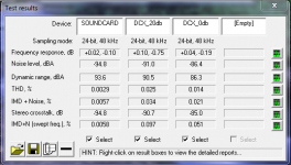
Soundcard is a Creative Audigy in slot 1. Slot 2 is through the DCX and attenuated 20db by my resistor divider in the xlr jacks. Slot 3 is through the DCX with no output attenuation.
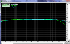
Frequency response:
THD for the DCX with 20db attenuation:
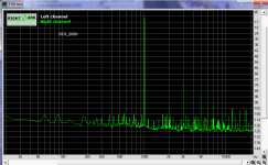
THD for the DCX with 0db attenuation:
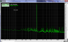
My unit is stock and a little more than a year old. I reset all of the channels to flat, input gain to 0, output gain to 0 and all filters and EQ off for the test. The test is on one channel only and RMAA is set for mono mode so pay no attention to crosstalk figures. I'm using the analog input "a" unbalanced. Output is also unbalanced (pin 1 tied to pin 3).
Results:

Soundcard is a Creative Audigy in slot 1. Slot 2 is through the DCX and attenuated 20db by my resistor divider in the xlr jacks. Slot 3 is through the DCX with no output attenuation.
Frequency response:

THD for the DCX with 20db attenuation:

THD for the DCX with 0db attenuation:

Thanks for those John.
Do I see a suppression on even order harmonics? And that your attenuated signal looks a little more even in harmonics than the 0dB?
Odd the slight roll off at the top of the attenuated signal. Not likely to notice it, but what would cause it?
(nice to see the old avatar back)
Do I see a suppression on even order harmonics? And that your attenuated signal looks a little more even in harmonics than the 0dB?
Odd the slight roll off at the top of the attenuated signal. Not likely to notice it, but what would cause it?
(nice to see the old avatar back)
Sounds fine to me. In fact it sounds the same (to me) as the signal unattenuated through my line receiver (shown a few posts back) to the amp. When I first got the DCX, I used it straight with the output unbalanced to the amp with volume attenuation from the source and this sounded just fine also.
If I had my time back, this is exactly how I would configure it in the beginning and save myself some work (and money). I have 6.8K in series and 680R to ground for ~20db attenuation.
Sounds like an easy solution, and looks like it reduces THD a bit as well. I see that someone mentioned this earlier in the thread. He called it a T-pad, but it is really an L-pad, right? Shouldn't the values be tailored to match the input impedance of the amps one is using (based on calculators like this one: L pad calculator )?
- Doug
Thanks for those John.
Do I see a suppression on even order harmonics? And that your attenuated signal looks a little more even in harmonics than the 0dB?
Odd the slight roll off at the top of the attenuated signal. Not likely to notice it, but what would cause it?
(nice to see the old avatar back)
Thanks, I'll wear this "face" for a bit.
THD is lower for the unattenuated, frequency response is a bit better and IMD is lower. Noise is up though, but not by much - still close to -90db. Looks like it is a better bet to leave the signal through the (stock) unit low. It would be interesting to run the same tests on a unit with the modified input and output stages.
I'm surprised by how much distortion the DCX adds, even with all of the DSP disabled. Using this formula: THD= SQRT ( (dist1*dist1) - (dist2*dist2) ) to subtract the soundcards THD gives worst case - 0.0248% and best case - 0.0137%. Can most of this be attributed to the output stage?
I don't know, but maybe we can figure it out.
Personally I don't worry much about THD, it's the harmonic structure that worries me. Old studies from the 20th century strongly indicate that high total amounts of distortion don't subjectively sound "bad", as long as the harmonics fall off in a regular manner.
The dominance of odd order isn't too surprising, given the push-pull nature of the circuit.
You've opened up a good avenue of investigation, I'll see if I can contribute.
-12db digital attenuation sounds worse than -0db at the same listening level
Excellent tests. But, I wouldn't automatically assume that the DCX will sound best with the amps wide open and large amounts of digital attenuation inside or preceding it. With my direct out modified DEQ, comparable in two channels to a DCX, a -12db digital gain setting in the utility menu sounds slightly more opaque and congested than 0db at the same listening level. As it would be expected. Large amounts of digital volume control is not transparent in my experience.
.
Signal path is EAD T1000 transport> Belden 1701A RCA to RCA> SRC2496 upsampling to 24/88.2 and converting to AES> 1701A XLR to XLR>Direct out DEQ> 1701A XLR pin 3 open to RCA> 4K switched shunt style attenuators on the amp inputs> Modified Sure 2X100 amp> Nordost flatline Gold 12 8 feet wires> DIY Usher 2 way.
.
Comparing -12db digital attenuation/-4db analog attenuation to -0 digital/ -16db analog reveals a slight loss of resolution with the increased digital attenuation even though the attenuators present a slightly more favorable load to the source when at -4db.
.
I am also still having a hard time accepting that the same loss isn't occurring in the ADC when intentionally leaving the analog input level low by 20db as you are not filling the available bits in the analog to digital conversion.
You're using just blocking caps on the chip output, right? How do you get from balanced to unbalanced - or do you?
This is certainly something to test. And it seems you've got a good start. Is there any sonic penalty to digital attenuation? If so, is it just with the DCX/DEQ attenuation, or would digital attenuation in signal coming from the player also hurt?
I've done some checking on this and have not drawn any hard conclusions, yet. More tests are in order.
- Home
- Source & Line
- Digital Line Level
- Behringer DCX2496 digital X-over
