You're welcome ") and pleased to hear you have one channel working.
and pleased to hear you have one channel working.
The 220 ohm... only Daniel can explain that one
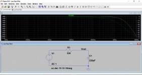
What it does do is interact with the 220pF cap to form a low pass filter although imo the effect of it is minimal with those values. If you turn the pot to a low value resistance, or even to zero ohms, then the 220pF cap effectively appears in parallel to whatever you connect to the input and in certain cases that might cause problems rather than help matters.
I would recommend fitting something like a fixed 1k resistor in place of the preset.
and pleased to hear you have one channel working.The 220 ohm... only Daniel can explain that one
What it does do is interact with the 220pF cap to form a low pass filter although imo the effect of it is minimal with those values. If you turn the pot to a low value resistance, or even to zero ohms, then the 220pF cap effectively appears in parallel to whatever you connect to the input and in certain cases that might cause problems rather than help matters.
I would recommend fitting something like a fixed 1k resistor in place of the preset.
Now I better understand, why I couldn’t hear any difference no matter the position of the potentiometer
My testspeakers are not the best but still.
With your explanation of the function of the cap and resistor I wonder why he put a potentiometer there instead of a fixed resistor.
My testspeakers are not the best but still.
With your explanation of the function of the cap and resistor I wonder why he put a potentiometer there instead of a fixed resistor.
You would have to ask Daniel that one
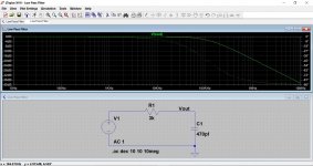
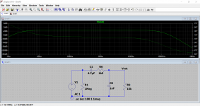
This shows graphically how the filter shapes the response. Look at the scale at the left. The second example would be more typical of values used in other designs.
One of the main functions of such a filter is to keep out interference.
This shows graphically how the filter shapes the response. Look at the scale at the left. The second example would be more typical of values used in other designs.
One of the main functions of such a filter is to keep out interference.
Attachments
Dear Gurus, I would be using 18v-0-18v 3A transformer; I would like to use fuses on the power supply module as well as on the amplifier modules. How much amperage should the fuses be rated at? Should they be the same? Also should I use slow-blo or fast-blo versions?
Thank you.
Thank you.

Common mode relates to a signal effectively appearing in series with both inputs.
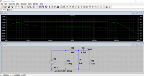
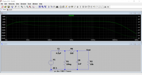
For minimum common mode gain (maximum rejection of common mode signals) both inputs need to see the same impedances over the range of frequencies involved. That means the 2.2uF, 470pF and 100uF's would have to go (DC coupled) and the 22k would need to be made equal to the 100k. You would also need a 2k7 in series with the input. The 560 ohm would need to be linked out.
So that just isn't practicable for that configuration.
It does exist!Can anyone please guide me which PCB to buy for gainclone? I am after most refined PCB which has ideal layout/component selection as per geeks here.
LM3886 Done Right
But, it doesn't use LM1875.
I had meant to get close, perhaps just for sport. In this case, I wanted the dividers at + and - to be same voltage proportions. The question is, did I get the input RF filter done right?Common mode relates to a signal effectively appearing in series with both inputs. For minimum common mode gain (maximum rejection of common mode signals) both inputs need to see the same impedances over the range of frequencies involved. That means the 2.2uF, 470pF and 100uF's would have to go (DC coupled) and the 22k would need to be made equal to the 100k. You would also need a 2k7 in series with the input. The 560 ohm would need to be linked out. So that just isn't practicable for that configuration.
Attachments
Last edited:
- Home
- Amplifiers
- Chip Amps
- Beginner's Gainclone, HiFi LM1875, The Amplifier Board