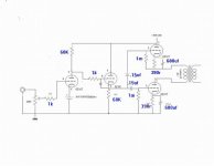
If the high-mu section wants to operate at a lower current than it is rated for and you want to keep the battery bias, you'll need to adjust the size of the 120k plate load so that the grid voltage on low-mu section in the output stage it as the right operating point. You can also increase the value of the cathode resistors in the output stage. What you need to do is get the grid-to-cathode voltage of your output section close that of Gary's. The final voltages are not as important as the difference between the two.
140-115 = 25V
Russ
140-115 = 25V
Russ
Hello,
Thanks for that, Russ.
I don't have any spare 10w resistors so I've been playing with different values for the plate load. It seems that ~360K gets me 23-25v between grid-cathode on the output section (it also plays music!). Voltages are also closer to original circuit.
Seems a long way off from Gary's circuit (and the suggested ~135K load for 6EA7/6EM7 types that I've seen mentioned in another forum).
Are there any implications in having such as high plate resistance (compared to the original spec)?
Thanks,
Chris
Yeah, like I said before it seems like these tubes have a weak high-mu section. It's hard to say how it might be working as the load line doesn't match the chart anymore. Without connecting the amp to a scope to check the input section's behavior, it's hard to say what may need to change.
By only changing the plate load, it further decreases the plate current because the plate voltage is going down while the grid bias is held constant by the battery. You can kick the plate current back up again by swapping some added resistance from the input plate load to the output cathode. That will move the output section cathode voltage up, allowing you to run a higher output grid voltage and thus a higher input plate voltage.
Lots of trace-offs with DC coupling.
Yeah, like I said before it seems like these tubes have a weak high-mu section. It's hard to say how it might be working as the load line doesn't match the chart anymore. Without connecting the amp to a scope to check the input section's behavior, it's hard to say what may need to change.
OK, Thanks.
I think I'm going to try and get hold of some replacement tubes and try again.
Chris
I have found that used 6EM7'S give quite unexpected voltages and really throw these direct coupled circuits out of whack. I got some new ones at a local supplier and they bias up just like the plate curves say they should.
I built one of Gary's amp's too. it sounds great!
Rolf.
I built one of Gary's amp's too. it sounds great!
Rolf.
Hello,
I've tried some alternatives and still suffered from higher voltages than those specified. After following Gary's advice of replacing the batteries with 1k pots I managed to get everything working correctly with the pots set to ~500ohm. I've got some more tubes in the post so will be experimenting with battery bias again soon.
At the moment I'm trying to sort out a hum problem that becomes apparent when B+ comes up and is the same regardless of the volume level. I've tried rotating the output transformers (James 6113hs) without luck.
Powering the amp up without the 6EM7s in place results in a very small level of hum (acceptably lower than with the tubes in place).
I'm going to investigate my ground wiring (I've tried a ground-lift resistor) and choke orientation.
The power transformer is a Hammond 370HX which gives out a small amount of mechanical buzz. It also gets quite warm after about an hour or so of operation.
Any suggestions would be appreciated.
Thanks,
Chris
Chris,
Hammond’s buzz and get quite hot if run close to full spec’ in my experience, so they may be the cause of mechanical buzzing but not any hum. Have you measured your hum at the speaker output jacks with a good AC meter? What is it?
You may get better help if you post a photo of the insides of your amp and a top shot of layout. Assuming you are using the power supply you linked in your first post, you should not get any “noticeable” hum, so most likely you have a ground issue or some cold solder joints. Is your input jack isolated from the chassis? Have you grounded the chassis with the ground wire from the wall? Are you tying your grounds together as suggested in the schematic? Chasing grounding gremlins just takes practice so expect to do a fair amount of soldering and resoldering.
Matt
Chris.
Nice wiring job! I see you used different chokes in the power supply, 8 Henries, I believe Gary's design called for 12? Also Being rated for 100 ma., they won't even achieve 8 Henries at 50 ma. or so. When I built mine I found the exact chokes Gary used at Nebraska Surplus Sales. My power supply came up short of 325 volts as well till I switched the 5v4g rectifier for a 5ar4 at Gary's suggestion. Very little hum from mine. I hope this helps.
Rolf.
Chris,
I forgot about that first photo. If things haven’t changed since then, you have left your output secondary hanging in the breeze with no ground reference. Try connecting your ground speaker lug to your circuit ground and see if that makes a difference.
It looks like the grounds of your input jacks get to your selector switch and then to ground. With your continuity tester make sure your RCA input jacks ground (all four) get to that common ground when they should given the switch position. Are you grounding your volume pot through the selector switch or its own ground? With your continuity tester is your volume ground always grounded no matter where the selector switch is?
On the five terminal strip at the bottom of the caps, reading left to right #2 looks to pick up your input grounds and voltage amp grounds and ties to #4, but I cannot see what the other lugs are doing. Is #1and #5 the 1.5K/1.3K resistor junction? It looks like it is. Your center lug, which is a natural ground to the chassis, is left open. Using clip leads and try connecting #2 and #4 together to see if there is a cold joint in that “Y”.
Where is the ground from the first capacitor connected? See if tying the first cap ground to the second cap ground with clip leads does anything.
Try clip leading your input jack ground to your speaker ground and to your circuit ground? Is there any continuity between your RCA jack ground and the chassis? It looks like those input jacks are isolated but sometimes the washer can slip so double check.
Is your input wiring three conductor, Red, Blue and Black (picking up right and left input grounds)? Do you have a foil shield? How did you hook that up?
Without knowing what your hum measurement is I don’t know if the lower value chokes are responsible for what you are hearing. You may want to read about “star-grounding” and give that a try.
Matt
In addition to the above suggestions you might just try paralleling an additional cap (say 47-100uf at 450v) with the caps after the chokes. I've always found that amps sound best with "just enough" capacitance to reduce the hum, but sometimes a bit more is necessary.
- Gary
- Gary
Hello,
Thanks for all the suggestions - I'll be working through these over the next couple of days. At the moment I've reworked the solder joints within the power-supply section and am currently tidying the amp section up which has become a bit of a mess over the last couple of weeks whilst trying to fix things.
The power supply is slightly different to Gary's. I've got 550ct TX -> 5v4g -> 32uF (2x16uF paralleled) -> 8H/259R/100mA Choke -> 32uF.
This is due to what I could get hold of at the time that would get me 325V. This was derived from PSUD (my first attempt at using this but seems to have worked with regards to getting the correct voltage).
A diagram of my input wiring can be found at www.erpland.com/inputwiring.JPG. This wiring configuration is the same as from a KT88 PP amp kit I built a few years ago.
Thanks again,
Chris
PSUD is great, a fantastic program.
I'd bet that increasing the capacitance after the choke won't affect the final voltage by more than a tiny amount. I'd try that as my first step.
You have a bit less capacitance and less inductance than I used - might be enough difference to give you the hum you're hearing.
My amp is quiet enough to be enjoyable with Altec A-5's, which are the acid test of any background hum or noise.
- Gary
Hello,
I've worked through the suggestions so far and replacing the final cap with a 50uF one (as per gary's circuit) has lowered the level of hum somewhat. There is still some hum which I would like to get rid off however.
Would it be worth paralleling a resistor across each cap to draw more current through the chokes to see if that improves things before trying a higher rated choke?
Regards,
Chris
I've worked through the suggestions so far and replacing the final cap with a 50uF one (as per gary's circuit) has lowered the level of hum somewhat. There is still some hum which I would like to get rid off however.
Also Being rated for 100 ma., they won't even achieve 8 Henries at 50 ma. or so.
Would it be worth paralleling a resistor across each cap to draw more current through the chokes to see if that improves things before trying a higher rated choke?
Regards,
Chris
Chris.
That's a really interesting idea. I would think, however, that you would be making a lot of heat and dragging down your power supply quite a bit. To get an extra 10 ma. through the choke at 325 volts, you will make 3.25 watts worth of heat and have that much more load on your power supply, probably reducing your B+ voltage a fair bit. I would think a bigger capacitor after the choke could only help. Too big a cap before the choke however will cause problems for the transformer and the rectifier tube.
Have you been able to source any new old stock tubes for your amp?
Cheers.
Rolf.
I would definitely try a larger cap after the choke and also make sure that charging currents from your first capacitor are not flowing through your ground wiring - to that end connect the center tap of you high voltage winding directly to the first filter cap and from there go to your common ground point - this will prevent ripple current modulation of your ground. (It can make a surprising amount of difference depending on your grounding scheme.) Make sure that you do not have more than one chassis ground point. (mecca ground) RCA jacks should be isolated from chassis.
On the issue you were having with the first triode in the amplifier, you probably have grid current issues, a 100K pot would significantly improve the situation. (To prevent a catastrophic melt down in the event the wiper goes open place a 220K resistor from wiper to ground.)
I am a member of the same audio circle as Gary and I have heard this amplifier, quite nice and quiet enough as Gary says to run an Altec A-5..
Edit: It looks like the power transformer center tap is going to the second capacitor in the filter chain? You'll want to fix that...
Thanks Guys for the suggestions.
Fair enough. The power transformer is already running a little warm so I won't make things worse by drawing additional, unnecessary current. I've ordered a couple more chokes (14H, 75mA, 429R) and will try these with a few changes to the power supply to get 325v.
I've got a few NOS National, Magnavox, RCA and Sylvanias that I snapped up off of e-bay.
I've changed my original 32u caps for 50u which seemed to improve things somewhat. I'll try connecting the (now spare) 32u caps after the new 50u ones to see if this improves things further.
The power transformer CT was connected to the first cap and then from there to the second (the first connection is hidden in the photo). I've now made this connection via a common star (the blue Y connection is now my star ground). I'm not sure if this has reduced the hum yet as I'm going to have to wait until later to test (my wife is watching TV at the moment).
Even with the hum (which isn't noticeable at louder levels) the amp sounds impressive. I don't think I'd ever get away with pair of those Altecs, though")
I've currently got the amp connected up to a pair of DIY Fostex FE167E BR boxes.
Thanks again,
Chris
That's a really interesting idea. I would think, however, that you would be making a lot of heat and dragging down your power supply quite a bit. To get an extra 10 ma. through the choke at 325 volts, you will make 3.25 watts worth of heat and have that much more load on your power supply, probably reducing your B+ voltage a fair bit. I would think a bigger capacitor after the choke could only help. Too big a cap before the choke however will cause problems for the transformer and the rectifier tube.
Fair enough. The power transformer is already running a little warm so I won't make things worse by drawing additional, unnecessary current. I've ordered a couple more chokes (14H, 75mA, 429R) and will try these with a few changes to the power supply to get 325v.
Have you been able to source any new old stock tubes for your amp?
I've got a few NOS National, Magnavox, RCA and Sylvanias that I snapped up off of e-bay.
I would definitely try a larger cap after the choke and also make sure that charging currents from your first capacitor are not flowing through your ground wiring - to that end connect the center tap of you high voltage winding directly to the first filter cap and from there go to your common ground point - this will prevent ripple current modulation of your ground. (It can make a surprising amount of difference depending on your grounding scheme.) Make sure that you do not have more than one chassis ground point. (mecca ground) RCA jacks should be isolated from chassis.
I've changed my original 32u caps for 50u which seemed to improve things somewhat. I'll try connecting the (now spare) 32u caps after the new 50u ones to see if this improves things further.
The power transformer CT was connected to the first cap and then from there to the second (the first connection is hidden in the photo). I've now made this connection via a common star (the blue Y connection is now my star ground). I'm not sure if this has reduced the hum yet as I'm going to have to wait until later to test (my wife is watching TV at the moment).
I am a member of the same audio circle as Gary and I have heard this amplifier, quite nice and quiet enough as Gary says to run an Altec A-5.
Even with the hum (which isn't noticeable at louder levels) the amp sounds impressive. I don't think I'd ever get away with pair of those Altecs, though
I've currently got the amp connected up to a pair of DIY Fostex FE167E BR boxes.
Thanks again,
Chris
Hello,
I've finally had a chance to work on the amp some more and ~130uF (made up from several caps) after the choke has fixed the hum problem. I can now hear only a very slight hum with my ears right up to the speakers.
I'll be trying battery bias again (once I manage to switch the amp off - it's sounding very nice) now that I've got a selection of tubes to experiment with.
Regards,
Chris
Hi.
Glad you got it tweaked to your satisfaction. I am listening to mine right now through 32 ohm headphones, sounds real nice.
I know how crazy making hum issues can be. I built a phonostage that defies all attempts to get it truly quiet. It is probably a fundamental flaw in my ground bus scheme. Since it is inaudible from my chair when actually playing music, I am not worrying about it.
You said before you where getting bigger chokes, did you end up using them or was the bigger cap enough?
I also built another amp that is the illegitimate love child of Gary's design and some articles by John Broskie. It uses about the same operating point for the output section and the same style of power supply except at 400 volts. At least it was supposed to be, it came out to 375. I am considering upgrading the power transformer at some point to correct this.
Here it is except that it now has led bias with the cathode followers load resistor tied to the first stage cathode. (no real change in sound from that)
Cheers.
Rolf.
Attachments
- Status
- This old topic is closed. If you want to reopen this topic, contact a moderator using the "Report Post" button.
- Home
- Amplifiers
- Tubes / Valves
- Beginners attempt at SE 6EM7