Agree 1000% !A wise person once said, "perfectionism is the enemy of progress". With speakers, like anything, you need to know what's important and what isn't.
Next questions shall be :
1) What is the recommended burn-in duration for a speaker, and what is the recommended signal to be applied on the speaker during the burn-in, for getting stable T/S parameters instead of the evanescent T/S parameters you may get upon unboxing the speaker ?
I think that I'll be able to handle this quite nicely when the time comes. What I've been trying so hard to solve lately, is, how can I in the least incorrect way, deal with that I will not be able to measure the bass drivers before I actually buy some and still do some simulations with them incorporated in my total system. Tweeters and mids are since a very long time waiting in my bookshelf for me to get going.
I've been in contact with the distributor in my country and we are both awaiting a reply from the manufacturer about the strange impedance curve I've received earlier for the bass drivers.
2) If we are measuring everything using a very very long FFT, taking much stimulation time, don't we face the danger that the loudspeaker is actually changing his T/S parameters during the measurement process, because of getting older ?
Now I must confess that I feel that I'm in deep water. I have huge difficulties interpreting nuisances in languages, and I don't take anything for granted no more, but my guess is that you are joking here, right?
I know the duration of a test tone can have huge impact on ones measurements. What kind of test tone to use, I hope to be able to get back to when that times come.
3) Regarding a SPL measurement, what is the room effect ? What is the magnitude of the room effect ? How to calculate this ? Do I need to know the Sabine coeffecients at 16,777,216 different frequencies, with a 24-bit precision ? Do I need to deconvoluate the room for isolating the pure loudspeaker response ? How to do this ?
This is very important considerations in my view, but they might all be of just academic value then the only room I've access to is my living room and from what I've seen, it does not correspond to the usual given requirements. I'll return to this issue later when measurements are to begin, to hear from you experienced builders, what, if any can be measured with some hope of getting the intended results, more than near field.
4) Regarding a SPL measurement, is there a kind of Fletcher-Munson correction to be applied for ensuring that the mike won't saturate at the lowest and at the highest frequencies, far away from the 1 kHz sensitivity figure ?
I wouldn't know, I only know that the mic I consider claim to conform to a couple of IEC classes and wouldn't know if any Fletcher-Munson corrections is needed, nor how to apply them if necessary.
5) What SPL should I use for graphing a loudspeaker Bode plot ? Can I set the SPL depending on my listening habits (loud or quiet) ? Shall I make five Bode plots, one at 70 dB SPL, one at 80 db SPL, one at 90 dB SPL, one at 100 dB SPL and one at 110 dB SPL ? I think I really need the 100 dB SPL curve because I like strong deep basses, and this looks like a Fletcher-Munson compensation. But I realize that very few speakers can deliver 110 dB SPL below 60 Hz. They saturate. What to do if all those curves don't run parallel in amplitude and if they are not surimposed in phase ? How many dB and how many degrees discrepancy are considered to be pathologic ?
Good questions, and it is considerations like this that gets my top to blow. My ignorance is enormous and so little time to learn. Where to start etc, etc. Maybe as I go along?
1. Perhaps this isn't essential?
No, it is not. I had misunderstood the use of that function completely.
2. you could try the SPL tracer at FRD Consortium
Good tip, I'll do that if I get a new curve to play with. If not, I'll need to consider a new bass driver.
3. You can either use the published T/S data and get close, which is often good enough, or break in your driver with some hours/days of excursion and measure the T/S yourself.
I've been into this earlier, the bass drivers have to be simulated as exactly as I can, before purchase and measurement because of their cost. I cannot afford to get it wrong, and with as good data as possible, I hope to be able to simulate them in the system good enough to be able chose suitable drivers when that time arrives.
4. Response flatness is probably more important. You don't necessarily need high levels to take measurements. Freedom from reflections and from noise is more important.
I agree, it is just that if needed, for SPL measurements, sometimes the mic needs to be able to handle a certain amount of dB's, and if that day arrives, I want to be prepared, if possible and I don't want plan everything according to my present abode, then I don't plan to live here forever.
So, do you disagree?
hi AllenB, I just want to make some fun, playing the same game buggsson is playing with us. Initially, trying getting everything quantified by hard science looked like a good idea. After a few iterations, we discovered that such attitude makes you go backwards 10 steps, after attempting making 1 step forward. The problem is that once you take such profile you need to stick with it forever, in everything.
steph, the sad thing is that I'm not playing a game, I wish I was, because you are correct in your description of my approach. I cannot stop trying to learn and I do not know when to stop, and I want to know everything, and that is everything, nothing less. This have been one of several reasons why I've progressed so slowly. However, your last sentence is incorrect, and in time I'll prove it. I've started the process, but it is hard, it is against my very nature, but I'll prevail otherwise the reaper will come for me before I plunge the router down into the first sheet of BB
I just wanted to illustrate how far this can lead to unproductivity. Each time you need to take a measurement comes the question of the enviromental effects, calibration, interpretation. You want to diy-build a loudspeaker in your kitchen, but just after turning your voltmeter on, you find yourself like a rocket scientist needing to solve the Heisenberg uncertainty principle, and uncover the nature of quarks, gluons and possibly Klingons also.
And still all of us need to remember that, even if a piece of software can display a nice result or a nice curve, appearing as "the definitive answer", this is not "the reality", but some unperfect input data being processed by a program, written by a programmer, having understood or not having understood the essence of the underlying algorithm, that was perfectly applicable or less perfecly applicable to the situation.
")
I agree, Steph, and I enjoyed your posts.
A wise person once said, "perfectionism is the enemy of progress". With speakers, like anything, you need to know what's important and what isn't.
Agree 1000% !
I agree as well ∞% to the above. And because I've written so much silliness already I'll just stop with:
"perfectionism is the enemy of progress". With speakers, like anything, you need to know what's important and what isn't."
and I don't, yet, but I hope to.
I am sorry for all my nonsence writing in response to steph_tsf's and AllenB's latest posts. They have nailed exactly what my problems have been up till now. I feel so good that I now have them out of my system more or less, so I finally can get started.
In the future, I'll hope to be able to stick to the subject.
Next hurdle will be to get my measurement system up and running. I'll order a mic today.
Hi buggsson, there is no nonsense in your approach. I respect your approach, truly. I want to encourage you. Your input has value.I am sorry for all my nonsence writing in response to steph_tsf's and AllenB's latest posts.
I'll order a mic today.
Has anyone mentioned the Behringer ECM8000 yet? I'm very pleased with mine.
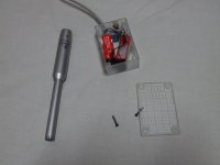
Measurement mike : need to talk about the Panasonic Electret Capsule WM-61A.
A measurement microphone for taking acoustic measurements using the Panasonic WM-61A electret.
A measurement microphone for taking acoustic measurements using the Panasonic WM-61A electret.
Then you need to boost the gain of your soundcard line-in. What signal/noise ratio do you get ? Don't you think you could get a 15 dB improvement in the signal/noise ratio by adding a +20 dB preamp consisting of a BC549C transitor, common emitter, output taken on the collector ?No preamp needed, Steph. I use two 9 volt batteries, two capacitors and a balanced connector. It runs straight into the line in on my soundcard.
So you know that you are deliberatly measuring and designing audiophile loudspeakers with measurement gear exhibiting a poor signal/noise ratio (by modern standards). Apparently, you don't feel the need for knowing the minimum signal/noise that's required for generating less than 1 dB deviation (or 0.2 dB deviation maybe ?) in the amplitude plots and less than 5 degree (or 1 degree maybe ?) in the phase plots. Surely, you know you may rely on averaging for boosting the measurements precision. You may feel more comfortable, if you apply the needed math for quantifying the whole question, don't you ?Perhaps, Steph, but I don't see the need to go down that road. I have all the signal to noise and gain that I need, and my sound card is fine. I can take meaningful measurements at a wide range of levels/times of the day. I feel my time is better spent building speakers.
I don't much care for the current tone of this conversation.
As far as I am concerned, I am not making irrational decisions. I am a qualified electronics technician. I have been interested in speakers for nearly forty years.
I am choosing not to respond to you in future unless you behave in a civil manner and stay on track.
As far as I am concerned, I am not making irrational decisions. I am a qualified electronics technician. I have been interested in speakers for nearly forty years.
I am choosing not to respond to you in future unless you behave in a civil manner and stay on track.
AllenB, I'm deeply sorry if you found offended, as this was not my purpose. Actually I was already googling about the signal/noise ratio needed from the measurement chain for a given dB/degree uncertainty. My intention was to see if the math were validating the common sense feeling that a 40dB signal/noise (20 Hz to 20 kHz) would be OK for 1dB precise measurements, even without averaging. But still, I think that connecting an electret capsule (delivering less than 10mV at 94dB SPL 1 KHz) directly on a sound card input (having a nominal sensitivity of 200mV or so), without a dedicated mike preamp, needs a carefull assessment. One must also know if the limiting factor of the signal/noise ratio is a) the (maybe) 90dB of your line-in less the 30dB that you are wasting with a direct line-in, b) the intrinsic signal/noise ratio of the mike capsule (there is a very cheap JFET inside), or c) the environmental noise like your fridge motor if you do the measurements in a kitchen. Cheers !
Last edited:
Common wisdom is that meaningful data may be extracted from as little as 10-12dB signal to noise with the proper treatment, such as averaging. That said, I can get 30dB signal to noise at 2 metres measuring distance, with my children asleep down the hall.
Now, I think it only fair that if this needs further discussion, you find an appropriate microphone thread, and PM me over to it.
Now, I think it only fair that if this needs further discussion, you find an appropriate microphone thread, and PM me over to it.
Ok, I'll do with pleasure.Now, I think it only fair that if this needs further discussion, you find an appropriate microphone thread, and PM me over to it.
Has anyone mentioned the Behringer ECM8000 yet? I'm very pleased with mine.
Yes, I know, lots of people are using it. I've also found people not so pleased about linearity and so forth, hence I've made another choice (see below).
Measurement mike : need to talk about the Panasonic Electret Capsule WM-61A.
A measurement microphone for taking acoustic measurements using the Panasonic WM-61A electret.
Well, this was my first choice and I am sitting on three capsules, aluminum tubes, XLR plugs, etc, etc. But considering my electronics skills (non-existent for now), and needing both the Linkwitz modification, a preamp if I am correct, and so far no calibration facility found where I live. Tons of speaker knowledge to catch up on, I'll buy (see below).
Behringer ECM8000 mike : need to explain the extra cost induced by a phantom-powered mike maybe ? Need to connect it on a phantom-power preamp. Next question : what phantom-power preamp ?
I hope to be able to buy me some time by buying the mic. I also have a phantom-power preamp:
MOTU.com - UltraLite-mk3 Hybrid Overview
The mic is one of the two I've linked to earlier:
iSEMcon GmbH
The data is a little bit different now compared to the web page.
SPL is up to 130dB and sensitivity is down to around 30mV/PA @ 94dBSPL from 50mV.
I've just realized that I've been so blinded by my thoughts on the microphone that it never occurred to me that in the mean time I could go forward with impedance measurements of my tweeters and mids, so that is what I'm planning to do next, so I'm back to the D'Appolito book again, chapter two.
I guess that I will go with the "The voltage-divider technique". I have a paper also describing how to do it (Williamsen, Speaker Builder 3/97). I hope the voltage divider is the only hardware you need, and that the frequency counter, sine wave oscillator can be used as software? Will a software based oscilloscope do for the zero phase measurements?
Other suggestions for measuring impedance?
I've also found people not so pleased about linearity
Yes, but it's all about priorities in a measurement mic. Spend more if you like.
Other suggestions for measuring impedance?
Use measurement software to send a test signal through the left output to your amp. Run your amp through a large resistance (to 1k) in series with your speaker under test. Left input to the soudcard comes from across the speaker. Calibrate the levels by temporarily replacing the speaker with a 10 ohm resistor and adjust so you get the spectrum at 10 of something (100mV for example).
The phase is similar only you need a reference. Use software to send a mono test signal through both outputs. Send the left through your amp, run your amp through a large resistance in series with your speaker under test. Left input to the soudcard comes from across the speaker. Right output is looped back to right input as a reference. Look at the phase of the complex transfer function of the two channels, ie: the difference between the two.
Yes, but it's all about priorities in a measurement mic. Spend more if you like.
Use measurement software to send a test signal through the left output to your amp. Run your amp through a large resistance (to 1k) in series with your speaker under test. Left input to the soudcard comes from across the speaker. Calibrate the levels by temporarily replacing the speaker with a 10 ohm resistor and adjust so you get the spectrum at 10 of something (100mV for example).QUOTE]
- I don't want to spend more, I have very irrational comfort zones despite trying very hard to be rational, and sometimes it costs me.
- Can you use any two-channel amp?
- What kind of signal to use, sinewave????
- For running in my mids, what kind of signal and freq. range? D'Appolito suggests 20-25 Hz range if I'm not mistaken, but that was for a LF-driver I think? Is the running in of a driver reversible? Say for example that a week passes between running in and measurement, go or no go?
- I have some stuff finding to do.
Yes. Set all controls to flat. Mind you dont overload your soundcard inputs when you set the levels. If you have any doubts you can use the standard calibration procedure of running a frequency response test thropugh the amp and back into the sound card which should give you a ruler flat result.- Can you use any two-channel amp?
Swept sine is good. Pink noise should work as well. The test signal should last a good few seconds.- What kind of signal to use, sinewave????
This procedure loosens the spider and roll surround. The driver stays that way. If you use the resonance frequency this will save you some amp power to get the driver moving. Push it as far as it will go without any stress.- For running in my mids, what kind of signal and freq. range? D'Appolito suggests 20-25 Hz range if I'm not mistaken, but that was for a LF-driver I think? Is the running in of a driver reversible?
If you use the resonance frequency this will save you some amp power to get the driver moving. Push it as far as it will go without any stress.
I am at a loss here, what is meant by "using the resonance frequency"? Instead of what? I don't think amp power will be an issue now, when I'm only doing my mids, but I would also like to understand the options, which I didn't know existed.
It seems that I have encountered some problems with assembling the jig material so I will have time thinking of other issues.
I've been thinking about baffle size for the MTM section. Regarding diffraction, I understand it so that the narrower baffle the better? I've calculated that I could do with a baffle approx. 7.5" (19 cm) wide. For hight I choose approx. 15.75" (40 cm) just so that I will be able to mount the drivers off center vertically, sidewise the distance will be the same.
I've also thought about chamfering. Linkwitz (I think it was) said that it is not of much use if the radius is smaller than 1/16 of the wavelength. The largest radius for a plunge router round over bit that I've found is 1.5" (38.1 cm). That would in that case take the effect down to around 1000-1100 Hz if my memory doesn't fool me and my calculations are correct.
When chamfering, how is the consieved width affected? The radius diameter would be 3". Will the baffle then be seen as wider if I would have to increase the width from 7.5", or is the edge seen as starting where the chamfer starts in the direction towards the edge?
I don't know if I've been clear enough, but I wonder because it will affect the baffle width input when trying to play with different diffraction scenarios.
I am at a loss here, what is meant by "using the resonance frequency"? Instead of what?
If you drive the woofer with a sinewave at the resonance frequency (ie: fs) of the woofer, you'll get the greatest cone movement for the least power input. It's all about economies. For example, the voice coil won't get so hot during the process.
Regarding diffraction, I understand it so that the narrower baffle the better?
This has a lot to do with the off axis response. It is in your interest to control the sound coming out at angles other than the one you're listening on, or at the least be aware of it and avoid extremes. All this sound goes into the room and finds its way back to you. This can mean that the sum total of all sound radiating at all angles can dictate the sound of the speakers, even if the on axis measures differently.
The idea of a narrow baffle is to encourage as much sound to radiate at all angles as possible to keep things even. ie: the sound will wrap around the baffle when its wavelength becomes comparable to the baffle dimensions. A narrower baffle lets more frequencies readily wrap around. My opinion is to hold the sound to a more narrow radiation pattern. I prefer a wider baffle that provides a launch platform for the lower midrange as well as just the higher frequencies covered by a narrow baffle. This is not essential, just making a point. You may have read that a narrow baffle improves imaging and I believe it can be done in other ways, and very well.
Imagine a wave travelling across the baffle from the speaker to the edge. When it reaches the edge, there is a sudden open area and the wave spreads around the edge. Sudden changes like this tend to cause a backlash. Part of the energy will be re-radiated from that point and things will become a little confused. Rounding the baffle reduces these reflections and improves sound.I've also thought about chamfering.
I find that using 'quad' or 'quarter round' mouldings can help.
I wonder because it will affect the baffle width input when trying to play with different diffraction scenarios.
There are two parts to the diffraction. The one most talk about is where the wavelengths of the lower frequencies outgrow the baffle size and wrap around it causing the on axis sound to be lowered (note that the total sound into the room remains the same). The other side is that the response can be a little rough even at higher frequencies, and you might want to experiment with locating the drivers on the baffle to balance this roughness a little.
I see a baffle diffraction simulator as being useful with the second point. If it is to be helpful, the simulator needs to be able to handle chamfering and rounding of the baffle as these affect the level of the diffraction. Some simulators can not do this.
Last edited:
- Status
- This old topic is closed. If you want to reopen this topic, contact a moderator using the "Report Post" button.
- Home
- Loudspeakers
- Multi-Way
- Before I start out, I need some direction