Some change of plans and their consequences
I'm back, but I'm still stuck as usual.
I've made some changes for my project since I last posted.
1. I've decided that I will abandon the two-box scenario and decided that I will do a one box system instead. I hope that will make it a bit easier for me. How the drivers will be configured is still open until some simulation is done.
2. The two Monacor MSH-16/4 mids will be run vented. In separate boxes (or tubes as the form factor will be) if MTM persists, and not change into MMT or TMM then they will be in a common tube.
3. I forgot to mention that I plan to do the woofers as push-push.
I have some major issues that I cannot find answers to regarding the vented solution the the Monacors.
I plan to cross them over actively at around 400 and 3600 Hz as of now. When I do some calculations for these drivers for vented applications, the fb usually ends up in the 90-100 Hz range. That seem to me to be unnecessarily low, but is that of no consequence in my case? No formula so far that I've come across accommodates the use of a user definable fb-value.
If ever, when do the vent become to large (in volume)? I was planning using a 2" diameter vent, but the Vd value is very small at 5.5 ml (55cm^2 x 1mm).
I've done some calculations according to LDC, and some others and a few online calculators. They all differ. I'm planning to take a few alternatives into SPEAK later on, but that feel kind of vague when I still don't fathom the two issues above.
If the final vents are too short, they will have to go on the baffle. Otherwise, what is the most preferable, baffle or backside?
Another issue I've tried to master, is to force me to be more focused and try to deal with one, or at the most, a few issues at a time. So this is my present "to do list"
1. Check if my mic. pre. is linear enough.
2. Buy the mic. and mic. amp. (or hopefully not, D.I.Y.the stuff)
3. Measure the mids (and the tweeters???)
4. Try to check the dispersion issues by using "Xdir"
5. Try to figure out the diffraction issues so I can decide on a baffle width by using "The Edge".
Something missing???
Last edited:
Congratulation for selecting two Monacor MSH-116/4 as medium drivers in a d'Appolito MTM configuration.
If you intend to run them 400 Hz to 3600 Hz you can put them in a 2 x 5,4 litre = 10,8 litre closed enclosure. This way you get a Bessel (Q=0.5) 2nd order acoustic lowpass transfer function with a -3dB point at 177 Hz. This is a reliable starting point.
Paramètres haut-parleur de THIELE et SMALL, sans filtre ni ampli
If your wife doesn't want to cope with 10,8 litres in the living room for the medium/high units, you may put the two MSH-116/4 in a smaller volume. If you put them into a 2 x 2,7 litre = 5,4 litre closed enclosure, you will get a Q=0.577 2nd order acoustic lowpass transfer function with a -3dB point at 167 Hz.
You need an electric highpass filter in order to isolate the MSH-116/4 drivers from the lowest frequencies. The lowest frequencies demand a high membrane excursion. The MSH-116/4 have a max excursion of only 2 mm. This is a decent however relatively small excursion compared to midbass drivers exhibiting a 4 mm excursion. Anyway, a 2 mm excusrion is much better than some old Fostex medium drivers exhibiting less than 1 mm linear excursion.
The 400 Hz cutoff frequency that you are targeting is nicely matching the 2 mm excursion of the MSH-116/4. You better select 340 Hz (this is still compatible with the 2 mm excursion) for getting the MSH-116/4 delivering a full decade (340 Hz to 3400 Hz) which is the telephonic frequency band used for speech.
Now you can design your electrical highpass filter. It must transform the natural (-3dB 177 Hz Q=0.5 or -3dB 167 Hz Q=0.577) acoustic highpass into an acoustic double butterworth (4th-order) highpass at 340Hz. Selecting the double butterworth as target enables you to step into the Linkwitz-Riley bandwagon, regarding the woofer to medium crossover arrangement.
If you use an active crossover you may apply an active Linkwitz "bass corrector" or "bass transformer" or "bass restorer" for transforming the natural acoustic response into the targeted double butterworth 340 Hz response.
Active Filters
2A & DIY
I'm attaching a .xls helping you calculating the components values.
This is a very handy circuit.
Make sure you enter the good values like not confusing a -3dB frequency point with a Fres frequency point. It is only for the butterworth case that the -3dB frequency point is equal to the Fres frequency point. As an example, the Fres frequency point of the 167 Hz Q=0.577 combination is 131 Hz.
Check it out again here :
Paramètres haut-parleur de THIELE et SMALL, sans filtre ni ampli
If you use a passive crossover you need to do the same job : transforming the natural -3dB 167 Hz Q=0.577 highpass response (Fres = 131 Hz) into a double Butterworth 340 Hz highpass.
With a passive crossover, make sure you connect an impedance compensation network in parallel with the drivers. Not doing this ruins the passive crossover behaviour.
You may opt for a basic RC impedance network corrector.
You may opt for a more accurate RLC impedance network connector.
Currently, I don't know if there is an analog circuit doing the same job as the active Linkwitz "bass corrector" or "bass transformer" or "bass restorer".
Will you check this out ?
How do I manage to do design the impedance corrector and passive crossover ?
Currently I'm using LTspiceIV.
Modelling the driver using the voice coil resistance, inductance, BL, suspension compliance, mobile mass, damping, and also the enclosure equivalent compliance (related to the enclosure volume and the membrane surface).
Adding on the LTspiceIV schematic a Sallen-Key opamp circuit delivering the target gain and phase curve.
Sallen?Key topology - Wikipedia, the free encyclopedia
Then, adjusting the L, R, C values of the passive crossover circuit using trial and test, for getting surimposed gain curves and surimposed phase curves.
This is time consuming, but quite enjoying.
Sometimes, after you are done with the gain and phase curves being surimposed, you run a global impedance plot (the impedance seen by the power amplifier) and you discover the very difficult task of the power amp. With the two 4 ohm drivers put in series, you may think that the amp will see a 8 ohm impedance. Well, if you suceeed in designing a perfect crossover, with perfect resulting curves, you may discover that the impedance can drop to 3.5 ohm. Then you realize the tradeoffs and compromizes commercial loudspeakers makers are forced to do. They can't pay for the coils. And they can't advertize 8 ohm nominal speakers having their impedance dropping below 4 ohm in specific frequency bands.
And this is only for the medium highpass filter.
And you still need to deal with the woofer lowpass (and possibly high frequency resonance dampers).
And you still need to deal with the tweeter highpass.
Now you need to decide about the woofer.
From what is stated above, the woofer acoustic response needs to be shaped as double butterworth 400 Hz lowpass. I guess that at this stage you know the theory of operation of the double buterworth of Linkwitz-Riley.
Targeting a 400 Hz double butterworth lowpass acoustic function is quite advantageous : you won't need a membrane made of unobtainium, exhibiting a linear frequency response until 4 kHz or more. Any decent polypropylene woofer up to 250 mm diameter will be good.
You wrote you would like to operate the woofers push-pull. Easier said than done ! Very important is to realize that with a 400 Hz lowpass, you won't be able to apply a subwoofer approach, like a 2 chamber 4th-order or a 3 chamber 8th-order (aka Bose). They have a natural cutoff around 120 Hz.
Thus, regarding the woofer, you will need to select a closed box arrangement (with an active Linkwitz bass corrector, or with a dual coil velocity feedback, or with a an piezo-based or MEMS-based acceleration feedback), or a conventional bass-reflex arrangement tuned at around 30 Hz. This is mandatory for a decent deep bass range restitution.
Believe me, you will waste your time and money if you don't set as goal of 30 Hz or 35 Hz restitution at -3 dB for the woofer.
For the tweeter crossover, you can chose between 1st order or Linkwitz-Riley double Butterworth (4th-order).
For the tweeter crossover, I suggest starting with a passive crossover 1st order, with a delay compensation network.
Such 1st order crossover only needs a coil in series with the medium drivers, and a capacitor in series with the tweeter.
The tweeter delay compensation network is a LC...LC ladder network made of 3 or 4 LC sections. Small inductors like 22µh, 33µH or 47µH are needed along with 1.0µF, 2.2µF, or 3.3µF capacitor. This is not expensive.
The tweeter delay compensation is mandatory for time-realigning the medium units with the tweeter, because of the recessed depth of the medium membranes. This is mandatory, but the commercial makers never implement this. They prefear fiddling with approximations in the crossover.
The 1st order crossover is quite demanding for a tweeter.
Even if you highpass filter at 3400 Hz, a frequency of 340 Hz will pass at -20 dB. This means that the tweeter will move a lot more than a few tens of microns. You may attain a few hundreds of microns.
Another decision-making facor is the phase response in the low range. Small tweeters like the Visaton CP13 (13 mm membrane and compact neodymium magnet) seem perfect for a d'Appolito MTM configuration with a minimal distance between the two medium drivers. See attached datasheet. Okay, that's very intersting, but their natural bahaviour is a natural 3000 Hz high-pass 2nd order. If you put a 10µF capacitor in series (with their own 4 ohm impedance), you define a 1st order high pass at 4000 Hz. But wait a minute : this means that between 3400 Hz and 4000 Hz we may approximate a 1st-order behaviour, but between DC and 3400 Hz, the behaviour will be 3rd-order.
You may then want to raise the crossover frequency to 8400 Hz : the regularity of the frequency response of the MSH-116/4 enable this. The capacitor in series with the Visaton CP13 would then be 4.7µF.
Never forget that the CP13 is not designed for a membrane excursion exceeding 100 microns. If you play 800 Hz at 50 volt peak-peak, remember that the tiny Visaton CP13 will see a voltage of 5 volt peak-peak after the 4.7µF highpass capacitor.
Remember that if you use a Linkwitz-Riley double butterworth crossover between the medium and the tweeter, the attenuation of the 800 Hz won't be 20dB anymore, but a whooping 80dB. Quite a difference !
As said before, this is the way I would start building the MTM units. Two Monacor MSH-116/4 and one Visaton CP13. With a passive crossover at 8000 Hz using a 4.7µF capacitor in series with the tweeter, and a small inductance in series with the medium units. Plus a LC..LC ladder network as delay compensation in the tweeter feed. The three units mounted as close as possible to each others. Almost no mechanical gap between the medium edges and the tweeter edge. A perfectly flat front face. Nothing protruding.
If you are not happy with this, after a few weeks you can unscrew your MSH-116/4 drivers and bolt them on a different front plate, compatible with one of those new 66mm high-quality tweeters from Tangband with a built-in rear chamber. Like Tangband 25-1719 or Tangband 25-1414SC. See attached datasheets. Those tweeters, once high-pass filtered at 3400 Hz using a 5.8µF capacitor in series (they may need an impedance compensation network in parallel), will strictly obey the 1st order highpass behaviour betweeen 800 Hz and 3400 Hz. Lowpass filtering the woofer at 3400 Hz will help inproving the polar radiation pattern, but remember that the two MSH-116/4 are now 66mm apart (instead of 30mm with de-ringed Viaton CP13), which may create new polar radiation pattern issues.
If during a loud disco party you find that your Visaton CP13 or Tangband 25-1719 or Tangband 25-1414SC tweeters are exhibiting saturation, then you will need the "king of the hill" tweeter from SB ACoustics. This is the SB25STAC-C000-4. See attached .pdf datasheet. It is also equipped with a rear chamber allowing him to deliver 680 Hz at -3dB, it delivers an outstanding polar radiation pattern, the bandwith extends far beyond 20 kHz without any accident nor resonance, and the linear coil travel is a huge 1.2 mm peak-peak. Again you will need to unscrew your MSH-116/4 drivers and bolt them on a different front plate, compatible with the 100mm tweeter frontplate.
Now you know that the height of your MTM box must be compatible with two Monacor MSH-116/4 medium drivers having one SB ACoustics SB25STAC-C000-4 tweeter inbetween. This way, going backwards, you can keep the same MTM box, only changing the frontplate and unbolting then re-bolting your MSH-116/8 medium drivers on alternate frontplates accomodating the 66mm Tangband tweeters or accomodating the ultraminiature 30mm Visaton CP13 tweeter. Always mount your medium drivers as close as possible.
This being said, you may try a double Butterworth Linkwitz-Riley crossover arrangement between the medium and the tweeter.
Your tweeter will thank you. It will see far less low frequency content, hence less membrane excursion as explained above.
But your ears may dislike a Linkwitz-Riley crossover between the medium and the tweeter. Because you lose the phase coherency. There is a huge phase shift occuring around the crossover frequency, equal to 360 degree. The system is not anymore "phase minimal". The waveforms get completely distorted in the time domain.
You may then ask why I've advocated for a Linkwitz-Riley crossover arrangement between the woofer and the medium.
We'll get a massive 360 degree phase shift around 340 Hz. The system is not anymore "phase minimal". The waveforms get completely distorted in the time domain.
The reason why I've advocated for a Linkwitz-Riley crossover arrangement between the woofer and the medium is because the MSH-116/4 medium have a limited excursion. Consider that if you play 34 Hz at 50 Volt peak-peak, the highpass attenuation with 340 Hz crossover frequency will be -80dB with a Linkwitz-Riley (5 millivolt) instead of -20dB (5 volt) with a 1st order highpass.
If you don't plan playing very loud music, the 1st order crossover arrangement at 340 Hz is an excellent audiophile choice. Regarding the woofer, if you are using a decent polypropylene membrane, you can expect a clean and smooth response untill 3400Hz, where the output of the lowpass is -20dB.
I'm still unclear with your idea of using two woofers in a push-pull configuration. I think you will be better, trying a plain and simple bass-reflex arrangement with one or two or three identical drivers mounted underneath the MTM box. For the woofer, you need to select a decent driver having a polypropylene or a well controlled paper membrane (no irregularities untill 3400 Hz), compatible with a -3dB frequency between 30 Hz and 35 Hz.
What woofer will you use ?
(all attachements in a .zip)
Steph
Attachments
Last edited:
Why aren't you going to run the Monacors sealed?
re:'The two Monacor MSH-16/4 mids will be run vented' - why? you'll have fewer phase/group delay problems if you use a closed box for the mids.
That intension came about due the quite high EBP (Small's invention) that comes in at just under 200, and where over 100 usually indicates that vented use would be a better idea. I thought that EBP was still good as a starting point, for both sealed and vented designs and I've heard you could do otherwise, but never seen an explanation as to why it is not necessary to follow the EBP praxis and the necessary actions you have to take (when applicable).
But if the common consensus is that sealed is better, I will jump at the idea because that is a so much simpler approach. I've just tried to delve into the mystics of vented designs and just to get the vent optimally designed is no small thing. Not to mension to be able buy it.
The Morel square 54mm x 54mm faceplate tweeters are now discontinued. As a consequence, the Morel MDT12 MDT22 MDT39 MDT40 and MDT44 are not available anymore.
They got replaced by the new CAT408 ET448 and ST728 fitted with a round 72mm faceplate.
Here is the summary regarding tweeters :
30mm : Visaton CP13 (most compact, 3 kHz highpass natural cutoff)
66mm : Tangband 25-1719, Tangband 25-1414SC (very compact, rear chamber, 800 Hz highpass natural cutoff)
72 mm : Morel CA408, Morel ET448, Morel ST728 (compact, rear chamber, 780 Hz highpass natural cutoff)
100mm : SB Acoustics SB25STAC-C000-4 (not compact, rear chamber, 680 Hz natural cutoff highpass, 1.2mm xmax linear travel peak-to-peak)
(attached round 72mm Morel tweeters datasheets in a .zip)
Attachments
1. If your wife doesn't want to cope with 10,8 litres in the living room for the medium/high units.
2. You need an electric highpass filter in order to isolate the MSH-116/4 drivers from the lowest frequencies. The lowest frequencies demand a high membrane excursion. The MSH-116/4 have a max excursion of only 2 mm.
The 400 Hz cutoff frequency that you are targeting is nicely matching the 2 mm excursion of the MSH-116/4. You better select 340 Hz (this is still compatible with the 2 mm excursion) for getting the MSH-116/4 delivering a full decade (340 Hz to 3400 Hz) which is the telephonic frequency band used for speech.
3. If you use a passive crossover. Currently, I don't know if there is an analog circuit doing the same job as the active Linkwitz "bass corrector" or "bass transformer" or "bass restorer". Will you check this out ?
4. With the two 4 ohm drivers put in series, you may think that the amp will see a 8 ohm impedance.
5. Now you need to decide about the woofer.
From what is stated above, the woofer acoustic response needs to be shaped as double butterworth 400 Hz lowpass. I guess that at this stage you know the theory of operation of the double buterworth of Linkwitz-Riley.
Believe me, you will waste your time and money if you don't set as goal of 30 Hz or 35 Hz restitution at -3 dB for the woofer.
6. Another decision-making facor is the phase response in the low range. Small tweeters like the Visaton CP13 (13 mm membrane and compact neodymium magnet) seem perfect for a d'Appolito MTM configuration with a minimal distance between the two medium drivers. See attached datasheet.
If during a loud disco party you find that your Visaton CP13 or Tangband 25-1719 or Tangband 25-1414SC tweeters are exhibiting saturation, then you will need the "king of the hill" tweeter from SB ACoustics. This is the SB25STAC-C000-4.
7. I'm still unclear with your idea of using two woofers in a push-pull configuration. I think you will be better, trying a plain and simple bass-reflex arrangement with one or two or three identical drivers mounted underneath the MTM box. For the woofer, you need to select a decent driver having a polypropylene or a well controlled paper membrane (no irregularities untill 3400 Hz), compatible with a -3dB frequency between 30 Hz and 35 Hz.
What woofer will you use ?
Steph
Steph, thank you for the long and detailed reply. It will take me quite some time to digest all of it. I'll start with the little I can reply to directly.
1. That volume is no problem, even though I never imagined that it would be that large. I was wondering about the tweeter and heat. It's a sealed and chambered tweeter, so does it need to have free space around for cooling, or is it possible to put in in a solid wood tube?
2. My spec. sheet says that Xmax is only +/- 1mm and not 2mm or did you mean the PTP excursion? 340Hz is fine by me as long as the excursion don't exceed the drivers excursion limit. That's why I choose 400Hz as a starting point in the beginning.
3. I will cross active.
4. I was planning to run the mids parallell, would in series be a better choice?
5. I'm sorry to say that I do not master the double Butterwoth Linkwitz-Riley theory at all, yet. I've read some papers so I understand some of it.
I do plan to play loud, and 30Hz at -3dB might be attainable.
6. Regarding tweeters, I went ahead of myself and baught what I imagined would be my best choice, without any solid ground for my decision. I bought a pair of Morel MDT 40. At least they have a rather small face plate at square 54mm. The C-C for the Monacors will be 91mm. Performance wise, I hope they will do.
I thought that I could try that MTM configuration on a separate box, made of 19mm particle board. Could such a box do the job?
7. I'm planning push-push for the woofers, not push-pull, in one chamber underneath the MTM.
Why do the woofers have to be able to so high as 3400Hz? Isn't that at least 3 octaves above 340Hz where they are to be crossed to the mids? For this kind of performance, I don't have any contenders. My contenders up till now are (and some lacks needed data at the moment):
1. Acoustic Elegance AV10H-D2
2. Creative Sound Solutions SDX10
3. SB Acoustics SB29NRX75-6
4. Dayton Audio RSS265HF-4´
5. SEAS Prestige L26RFX/P
And being 10" woofers, I don't want to use PP-cones, so if these should turn out to be unusable, I don't know where to look.
And now I have a ton of new information and suggestions to digest, so I'm gonna be a while I guess.
A miniature tweeter has less surface than a regular tweeter. This is maybe the reason why Morel just discontinued the small 54mm x 54mm tweeters, replacing them by round 72mm models. Internally, they remain the same, with same membrane and same voice coil. The front face of the tweeter may help dissipating heat, if is it made of aluminium. You may be right in saying that encapsulated tweeters having a rear (closed) chamber can have issues regarding cooling. It all depends the SPL you are targeting. If you want to play very loud, go for the SB Acoustics SB25STAC-C000-4 tweeter. Remember that, with a 100mm diameter, the SB Acoustics SB25STAC-C000-4 tweeter forces you to put the MSH-116/8 medium drivers more apart than the 30mm Visaton CP13, 66mm Tangband 25-1719 or Tangband 25-1414SC, or 72 mm Morel CA408, Morel ET448 or Morel ST728.
You are right regarding the xmax specification of the MSH-116/4. It reads linear xmax +/- 1mm hence 2mm peak-to-peak. Other makers, most of the tilme, don't tell you if the quoted xmax is 1) the peak amplitude, the peak-to-peak value (which is twice) or the RMS value (which is inbetween) and b) the linear limit or the physical limit.
When you say that you will cross-active, do you mean 2 amps or 3 amps per channel ?
Each mid has a 4 ohm impedance. You better wire them in series for getting a nominal 8 ohm impedance, compatible with any kind of power amplifier. If you wire them in parallel you will get a 2 ohm impedance.
A wise decision would be to use the Morel MD40 tweeters that you already bought, with a 74mm distance between the MSH-166/4 medium drivers. This will allow mounting the newest round 72mm Morel tweeters in case you need to build more than one system. The Morel MD40 tweeters are now discontinued.
Sorry for misreading your "push-push" as "push-pull".
With two 10 inch bass drivers in a bass-reflex arrangement you should be able to reach all your objectives regarding bass rendition. I have not yet studied the Thiel & Small parameters of the bass drivers you have preselected. Please attach a .zip file or a .xls file listing the Thiele & Small parameters.
If you want to have a chance succeeding with a linear phase 1st order crossover allround you better use two 8 inch (20 cm) bass drivers wired in serial (if they are 4 ohm) or parallel (if they are 8 ohm). Nearly all polypropylene bass drivers having a diameter of 8 inch (20 cm) have a very smooth high frequency natural roll-off. A few old-school paper-based membrane woofers also exhibit the same qualities, but they tend to be more expensive nowadays than polypropylene woofers, and less easy to find. Unfortunately, the difficulty with the bass reflex arrangement is that you need a very specific combination of membrane mass, suspension compliance and BL for enabling a 30 Hz or 35 Hz restitution at -3dB with a realistic cabinet size and with a realistic vent size. You may end up concluding that, in general, paper-based membrane are better suited, with their small mass, than polypropylene membranes.
I'm not a big fan of side-firing woofers. I'm however guessing this is what you want to do. Your "push-push" idea is to neutralize the parasitic inertia forces and tremors with the two drivers firing in the opposite direction. And you thus need to fire laterally because you don't want one of the two woofers firing on the rear wall of your listening room.
Why am I against side-firing woofers ?
Because the emission point is not anymore accurate. It lies "somewhere", "virtually" in the middle inside your cabinet for the medium range, for the frequencies where the vent contribution is zero (say 100 Hz to 340 Hz). And it lies "somewhere" inside your vent(s) for the deep bass range where the vent contribution is dominant (say 35 Hz to 100 Hz)
This array of negative features is already naughty when you consider your bass unit as a 30 Hz to 340 Hz sound generator.
But try now to represent what's happening in the transition band, when the 240 Hz to 440 Hz needs to accurately blend with the two MSH-116/4 medium drivers !
And now, what if you go for a 1st order crossover between the bass and the medium. In such case, the transition band extends from 170 Hz to 680 Hz. What a mud !
If you want your bass to blend smoothly, invisibly, with the medium, there is only one solution : get the two bass drivers firing in a normal way, like the two medium drivers. And pay attention to the location of the vent. It must be considered as an acoustic source also supposed to blend smoothly, invisibly, with the sound emitted by the bass drivers membranes.
Heavy 19mm wood panel will help you battle against inertia forces and tremors.
A separate MTM box plus a separate bass box is the way to go. Make your wife happy by selecting the same width for both boxes. This way, when you put the MTM on top of the bass box (this gives the best listening results), she will have the impression that your new toy is like any other column speaker she can see in any hifi shop.
Please post a reply, listing the Thiele & Small parameters (or datasheets) of the woofer drivers you have preselected.
Steph
Last edited:
The thermal management of a tweeter is an interesting theme.
Heat gets generated in the coil.
A small fraction of the heat is transferred to the magnetic polar pieces using thermal radiation within the magnetic gap. Because the polar pieces are so close to the coil. The more the coil is close to the polar pieces (a narrow magnetic gap demands high precision engineering), the more the magnetic polar pieces will function as heatsink.
If there is ferrofluid in the magnetic gap, more heat gets transferred to the magnetic polar pieces, this time using thermal conduction.
The rest of the heat gets transferred to the coil former, which is mechanically connected to the membrane.
In a dome tweeter, there is no spyder. In a cone driver, there is a spyder. The spyder gets connected to the coil former. If the spyder is made of a heat-conducting material, the spyder may act as supplementary heatsink, conveying the heat to the outer structure.
If the tweeter membrane is made of metal, the membrane functions as an important heatsink. The heat propagates radially from the coil former connecting point, to the outer edge of the membrane.
If the outer suspension is also in metal, the heat then propagates to the front plate of the tweeter.
Now you understand why aluminium tweeters with an aluminium suspension are capable of dissipating 100 watt. The whole front plate (usuallly 100 mm in diameter in aluminium) gets used as main heatsink. Because there is a metal continuity linking the surface where the heat gets generated (the coil then the coil former), to the surface where the heat gets dissipated (the whole 100mm diameter front plate).
1. You may be right in saying that encapsulated tweeters having a rear (closed) chamber can have issues regarding cooling.
2. When you say that you will cross-active, do you mean 2 amps or 3 amps per channel ?
3. Each mid has a 4 ohm impedance. You better wire them in series for getting a nominal 8 ohm impedance, compatible with any kind of power amplifier. If you wire them in parallel you will get a 2 ohm impedance.
4. With two 10 inch bass drivers in a bass-reflex arrangement you should be able to reach all your objectives regarding bass rendition.
If you want to have a chance succeeding with a linear phase 1st order crossover allround you better use two 8 inch (20 cm) bass drivers wired in serial (if they are 4 ohm) or parallel (if they are 8 ohm). Unfortunately, the difficulty with the bass reflex arrangement is that you need a very specific combination of membrane mass, suspension compliance and BL for enabling a 30 Hz or 35 Hz restitution at -3dB with a realistic cabinet size and with a realistic vent size.
If you want your bass to blend smoothly, invisibly, with the medium, there is only one solution : get the two bass drivers firing in a normal way, like the two medium drivers. And pay attention to the location of the vent. It must be considered as an acoustic source also supposed to blend smoothly, invisibly, with the sound emitted by the bass drivers membranes.
5. A separate MTM box plus a separate bass box is the way to go. Make your wife happy by selecting the same width for both boxes. This way, when you put the MTM on top of the bass box (this gives the best listening results), she will have the impression that your new toy is like any other column speaker she can see in any hifi shop.
Steph
1. That was more a question I would like to have answered due to construction issues with the MTM section. It might be void now however, due to the much larger box/es for the mids than I first anticipated.
2. 3 amps.
3. I was thinking parallell to get the dB@1W 1m to get them more in line with the tweeter, but that might not be such an issue when crossing actively?
4. I was thinking of crossing the woofers to the mids with a 4th order filter due to its steepness of the slope and I've been so into sealed solutions that I've not looked into woofers for vented applications, and not much about vented at all.
I did a calculation for a vented application á la Dickason (QL = 7) for the AE Speaker woofer and got:
Vb = 70 liters
fB = 27,7 Hz
f-3 = 26,1 Hz
Vent diameter = 4.15" (vent length remains to be done)
5. I was thinking of abandoning the two-box system due to ease of construction. I've yet to come across a suitable solution or advice for how to attach the MTM box to the woofer box where minimizing space between the boxes is a priority.
I hope the links to the woofer data below will be satisfactory.
The Dayton woofer lacks measured data below 200Hz and for the CSS driver I have received measurement files, but they are at home. The cone break up is at 1500 Hz according to the information I got. The AE speaker do not have any measurement that I know of as yet, but is said it should work for my application.
Acoustic Elegance Speakers:
Acoustic Elegance • View topic - AV woofer parameters and dimensions
Creative Sound Solutions:
http://creativesound.ca/pdf/CSS-SDX10-data-140408.pdf
SB Acoustics:
SB Acoustics :: 10" SB29NRX75-6
Dayton Audio:
http://www.parts-express.com/pdf/295-460s.pdf
SEAS:
THE ART OF SOUND PERFECTION BY SEAS - H1209-08 L26RFX/P
You may try this tweeter also :
JBL Factory Speaker Replacement Tweeter 027Ti
Don't know if the membrane is a tinanium one with integral suspension.
Don't know if the front plate is in metal.
You may rework the front plate for making it round.
If this appear to be a "full metal" tweeter, thermal management would be optimal.
Check it out !
I did a calculation for a vented application á la Dickason (QL = 7) for the AE Speaker woofer and got:
Vb = 70 liters
fB = 27,7 Hz
f-3 = 26,1 Hz
Vent diameter = 4.15" (vent length remains to be done)
any reason the SEAS CA26RE4X has not been short listed. It's EBP ratio would suggest bass reflex.
THE ART OF SOUND PERFECTION BY SEAS - H1316-08 CA26RE4X
When you deal with a bass-reflex box, you need to remember the physical nature of the things.
Bass-reflex means :
- a box volume expressed in litres (from 5 litre to more than 100 litre)
- a vent air mass expressed in grams (from 5 gram to more than 100 gram)
It is only after you complete your design (deciding about the box volume and deciding about the vent air mass) that you decide the shape of your vent.
You may opt for :
- a short "gold number" vent (diameter = 1.618 * lenght)
- a long "gold number" vent (lenght = 1.618 * diameter)
Practically, you need to use ready-made tubing. Select a close approximation to what you need in ABS plastic tubing used by plummers. It works, it is widely available, and it is inexpensive.
ABS Pipe - ABS PIPE - Order Online - Buy
More JBL Titanium tweeters here (or copies) :
http://www.simplyspeakers.com/replacement-speaker-tweeter-t-336.html
http://www.simplyspeakers.com/replacement-speaker-tweeter-t-338.html
Last edited:
buggsson said:4. I was thinking of crossing the woofers to the mids with a 4th order filter due to its steepness of the slope and I've been so into sealed solutions that I've not looked into woofers for vented applications, and not much about vented at all.
5. I was thinking of abandoning the two-box system due to ease of construction. I've yet to come across a suitable solution or advice for how to attach the MTM box to the woofer box where minimizing space between the boxes is a priority.
Because of the crossover frequency you will be using, you'll have some freedom in choosing the height of the mids over the woofers, and choosing the crossover slope. You may yet benefit from the simplicity of a more shallow slope, even if it gets steeper out of band.
any reason the SEAS CA26RE4X has not been short listed. It's EBP ratio would suggest bass reflex.
Just because I've just started to considerate vented options
When you deal with a bass-reflex box, you need to remember the physical nature of the things.
Bass-reflex means :
- a box volume expressed in litres (from 5 litre to more than 100 litre)
- a vent air mass expressed in grams (from 5 gram to more than 100 gram)
It is only after you complete your design (deciding about the box volume and deciding about the vent air mass) that you decide the shape of your vent.
You may opt for :
- a short "gold number" vent (diameter = 1.618 * lenght)
- a long "gold number" vent (lenght = 1.618 * diameter)
This is new to me. I recall having seen something about vent air mass, but not in the calculations I've used or know of. Do you have any suggestion where I can find info for this way to do calculations?
I've seen so many different formulas and on-line calculators that my eyes are sore, and I apparently still don't know which to use. I've among others, tried Dickason in LDC and http://mh-audio.nl/ReflexBoxCalculator.asp (according to W. J. J. Hoge's Business Pages) but neither uses this way of doing it.
The "gold numbers", I don't understand how you get to the diameter to start with? Sometimes I really wish that I could take the first on-line calculator I could find and be done. For now I'm running i circles and looking for "The Way" to follow.
Everything simplifies when simulating the whole system (active crossover, power amp, speaker drivers, enclosures and vents) using LTSpiceIV.
http://www.diyaudio.com/forums/multi-way/167341-need-advice-about-monacor-drivers.html
Please take some time installing LTspiceIV on your computer, copying the above simulation files in a directory, and running the simulation.
There is plenty of information about how to use LTspice.
Linear Technology - Design Simulation and Device Models
Please download all files : Download LTspice IV (Updated November 16, 2010) , LTspice Users Guide, LTspice Getting Started Guide, LTspice Demo Circuit Collection.
In this practical case study, with all simulation files provided by me, with all subcircuits models provided by me in the same directory, it is a piece of cake. You only need to know which button you need to press in the LTspiceIV user interface.
You'll be impressed.
When was it last time you could graph the gain, the phase and the group delay in function of the frequency, for a 2-way system with active filtering ?
Later on when you get used to the 2-way system simulation using LTspiceIV, I'll create a template for your 3-way system with active filtering.
Because of the crossover frequency you will be using, you'll have some freedom in choosing the height of the mids over the woofers, and choosing the crossover slope. You may yet benefit from the simplicity of a more shallow slope, even if it gets steeper out of band.
What would the benefit of a shallower slope be in comparison, and how much shallower?
Everything simplifies when simulating the whole system (active crossover, power amp, speaker drivers, enclosures and vents) using LTSpiceIV.
http://www.diyaudio.com/forums/multi-way/167341-need-advice-about-monacor-drivers.html
Please take some time installing LTspiceIV on your computer, copying the above simulation files in a directory, and running the simulation.
There is plenty of information about how to use LTspice.
Linear Technology - Design Simulation and Device Models
Please download all files : Download LTspice IV (Updated November 16, 2010) , LTspice Users Guide, LTspice Getting Started Guide, LTspice Demo Circuit Collection.
In this practical case study, with all simulation files provided by me, with all subcircuits models provided by me in the same directory, it is a piece of cake. You only need to know which button you need to press in the LTspiceIV user interface.
You'll be impressed.
When was it last time you could graph the gain, the phase and the group delay in function of the frequency, for a 2-way system with active filtering ?
Later on when you get used to the 2-way system simulation using LTspiceIV, I'll create a template for your 3-way system with active filtering.
Thanks, I do hope it's as easy as you say.
Is there a difference in expressing the vent in grams vs. volume, and where can I find a paper, book or other source describing the vent in grams?
Anyway, I've reprinted Small's and Thiele's vented box papers for starters and will pay attention to Spice when at home.
A shallower slope offers less processing of the sound with less components, and is less critical to small errors in matching the drivers.
As far as slopes, it depends but it already looks like with a second order filter on the mid you'll already get somewhere between a second and a fourth order acoustic rolloff with the sealed enclosure. You'd typically then try to match that with the woofer. Assuming it is a fourth order rolloff, you may want to get your extra second order of electrical filtering done out of band.
As far as slopes, it depends but it already looks like with a second order filter on the mid you'll already get somewhere between a second and a fourth order acoustic rolloff with the sealed enclosure. You'd typically then try to match that with the woofer. Assuming it is a fourth order rolloff, you may want to get your extra second order of electrical filtering done out of band.
Physically, in a bass-reflex box, the vent operates as a volume enclosing an air mass :
temp °C and the corresponding air density (kg per cubic meter)
+35 -> 1.1455
+30 -> 1.1644
+25 -> 1.1839
+20 -> 1.2041
+15 -> 1.2250
+10 -> 1.2466
from : Density of air - Wikipedia
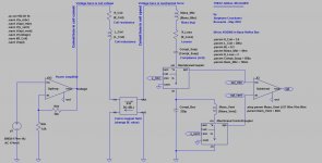
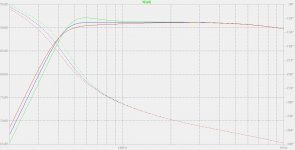
In the LTspice equivalent schematic, the vent is represented by an inductance. The value of the inductance is the air mass.
This mass interacts with the box volume, creating the bass-reflex resonance. As you may have noticed, the box volume (corrected by a factor linked to the speaker surface) translates into a compliance, represented by a capacitor in the LTspice equivalent schematic.
This forms a LC resonating circuit, hence the existence of a "vent resonance frequency". I'm using brackets because there is a misrepresentation in this. The vent has no resonance frequency by itself. It is only when combining 1) the vent air mass to 2) the box volume + speaker surface that you get a LC system leading to resonance.
In the LTspice equivalent schematic, the current flowing into the inductance is the speed of the air mass, moving back and forth into the vent.
SPL is proportional to the time derivative of the air mass speed (or air volume speed).
Which means that SPL is proportional to the air mass acceleration (or air volume acceleration).
The air mass SPL combines in phase and in amplitude with the SPL generated by the speaker membrane.
Actually, for very low frequencies (like 2 Hz or 5 Hz), the combination is not an addtion. It is a substraction.
Why ? Consider the woofer membrane. Inject a DC current into the woofer in such a way that the woofer membrane moves OUT. There is thus a depression created into the box. As a result, the vent air mass will fill the depression. The vent air mass will thus flow INTO the box. Same for very low frequencies up to 10 Hz or so. A 180 degree phase shift between the membrane SPL and the vent SPL, leading to mutual cancellation.
This is why, in the LTspice equivalent schematic, there is a substractive combiner wired on the membrane SPL output and on the SPL air mass output.
Actually, when you raise the frequency, you get a different phase shift between the membrane SPL output and the SPL air mass output. When the phase shift is 360 degree instead of 180 degree, the outputs combine positively.
The membrane-vent interaction is so important that for a certain frequency, which is the bass-reflex resonance frequency, the woofer membrane excursion gets internally counteracted by the internal counter-pressure coming from the vent.
See attached pictures.
The Mivoc AW2000 woofer is here : Mivoc AW 2000
temp °C and the corresponding air density (kg per cubic meter)
+35 -> 1.1455
+30 -> 1.1644
+25 -> 1.1839
+20 -> 1.2041
+15 -> 1.2250
+10 -> 1.2466
from : Density of air - Wikipedia
In the LTspice equivalent schematic, the vent is represented by an inductance. The value of the inductance is the air mass.
This mass interacts with the box volume, creating the bass-reflex resonance. As you may have noticed, the box volume (corrected by a factor linked to the speaker surface) translates into a compliance, represented by a capacitor in the LTspice equivalent schematic.
This forms a LC resonating circuit, hence the existence of a "vent resonance frequency". I'm using brackets because there is a misrepresentation in this. The vent has no resonance frequency by itself. It is only when combining 1) the vent air mass to 2) the box volume + speaker surface that you get a LC system leading to resonance.
In the LTspice equivalent schematic, the current flowing into the inductance is the speed of the air mass, moving back and forth into the vent.
SPL is proportional to the time derivative of the air mass speed (or air volume speed).
Which means that SPL is proportional to the air mass acceleration (or air volume acceleration).
The air mass SPL combines in phase and in amplitude with the SPL generated by the speaker membrane.
Actually, for very low frequencies (like 2 Hz or 5 Hz), the combination is not an addtion. It is a substraction.
Why ? Consider the woofer membrane. Inject a DC current into the woofer in such a way that the woofer membrane moves OUT. There is thus a depression created into the box. As a result, the vent air mass will fill the depression. The vent air mass will thus flow INTO the box. Same for very low frequencies up to 10 Hz or so. A 180 degree phase shift between the membrane SPL and the vent SPL, leading to mutual cancellation.
This is why, in the LTspice equivalent schematic, there is a substractive combiner wired on the membrane SPL output and on the SPL air mass output.
Actually, when you raise the frequency, you get a different phase shift between the membrane SPL output and the SPL air mass output. When the phase shift is 360 degree instead of 180 degree, the outputs combine positively.
The membrane-vent interaction is so important that for a certain frequency, which is the bass-reflex resonance frequency, the woofer membrane excursion gets internally counteracted by the internal counter-pressure coming from the vent.
See attached pictures.
The Mivoc AW2000 woofer is here : Mivoc AW 2000
Attachments
Last edited:
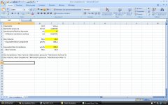
I guess you are going to ask how to calculate the equivalent Box Compliance in function of the Box Volume and Membrane Diameter.
The maths are based on the Boyle-Mariotte law saying that for ideal gases, P*V = constant.
with P = pressure
wth V = volume
All this, when keeping the temperature constant.
Consider a closed volume (the Box Volume) equipped with a moving membrane (Membrane Surface). If you press the membrane inwards, you will feel a counteracting force. This counteracting force is pneumatic. It is not coming from the loudspeaker suspension. If you press the membrane inwards, you raise the internal pressure. The counteracting pneumatic force is equal to the internal pressure raise, multiplied by the membrane surface. So simple !
You will be right in saying that this process is non-linear.
Non-linear because there is a math division in the process, a 1/x factor.
In the PV = cst context, you decrease V (you push the membrane inwards) and as output you get an inflated P (more internal pressure).
If you divide the volume by 1.01, you get a pressure multiplied by 1.01.
The well accepted trick is that whole thing reduces to a linear approximation if the variations are kept very small.
We need to live with this.
Must say that sound in an appartment, are indeed very small pressure variations compared to the ambiant barometric pressure.
Speaking about small variations, one way to get the formula is to differentiate the Boyle-Mariotte P*V = constant equation, and neglect the high-order terms :
dP = (P_init / V_init) * Membrane Surface * dX
with dX being equal to the membrane displacement.
Then you express the force generated by dP, because of the Membrane Surface :
dF = Membrane Surface * dP
And then, you combine the two expressions for getting the compliance, knowing that the compliance is equal to dx / dF.
See attached picture
See attached .zip
The zip contains the .xls spreadsheet.
Attachments
Last edited:
- Status
- This old topic is closed. If you want to reopen this topic, contact a moderator using the "Report Post" button.
- Home
- Loudspeakers
- Multi-Way
- Before I start out, I need some direction