If you add an adjustable DC offset circuit (similar to Krell KSA-50 https://elektrotanya.com/PREVIEWS/63463243/23432455/krell/krell_ksa50_sch.pdf_1.png), you should be able to adjust the DC offset to +/- 10mV after the amp warms up. Alternatively, you can use an op-amp and add a DC-servo circuit: DC Servos
Otherwise +/- 70mV is not bad as is. The old Hafler 200's had 300mV offsets which is why Hafler 220 added a DC-balance circuit: https://hafler.com/pdf/archive/DH-220_amp_man.pdf
Good luck.
Otherwise +/- 70mV is not bad as is. The old Hafler 200's had 300mV offsets which is why Hafler 220 added a DC-balance circuit: https://hafler.com/pdf/archive/DH-220_amp_man.pdf
Good luck.
If you add an adjustable DC offset circuit (similar to Krell KSA-50 https://elektrotanya.com/PREVIEWS/63463243/23432455/krell/krell_ksa50_sch.pdf_1.png), you should be able to adjust the DC offset to +/- 10mV after the amp warms up. Alternatively, you can use an op-amp and add a DC-servo circuit: DC Servos
Otherwise +/- 70mV is not bad as is. The old Hafler 200's had 300mV offsets which is why Hafler 220 added a DC-balance circuit: https://hafler.com/pdf/archive/DH-220_amp_man.pdf
Good luck.
Thank you Vilfort for the Krell schematic. I am also playing with the idea of rebuilding the Bedini circuit later. I might integrate something like that there. For now, I think that anything that stays below 50mV should be sufficient. The Hafler example also seems to confirm this. Since the offset for each of the channels is more or less the same, I am not assuming an audible imbalance and the low DC voltage will probably not damage the stepup transformer of my Quad ESLs either.
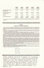
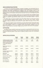
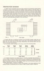
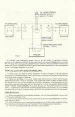
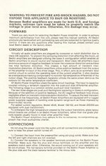
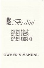
Here's the Owners' Manual if its any help
Thank you WorriedInitial for the nice owners manual! There is also mentioned an "impedance monitoring device" to limit power at low impedances, which seems to point to the 5K6 resistor/z-diode combination. I assume it does not refer to the output fuse ;-)
Last edited:
Hi Markus,
I would replace the 1n4751 zeners with 1n4742. This is in line with the original Bedini design that limited the voltage for the differential pair to 12 V. I had the diff-pair failing a few times because the voltage was too high. I have BC550/560s here because the MPS8xxx series was not readily available here in South Africa. After a lot of searching around and speaking to a few people more recently, another alternative here are the ZTX450/550.
As you pointed out, you have matched these diff-pairs. My Bedini original trafo (E-core) was very definitely wound for 20 Volts. The mains voltage is slightly higher here in Pretoria (235 V) so my secondary rails were at 21.4 volts not connected and 28 V connected to the amp PCBs. From what I can recall (15 years ago) when I tested the output offset it normally measured at roughly 60 mV on each channel.
The one thing I do not see is the two 3 Ampere diodes that are connected from the PSU rails to ground. This was a modification to the original circuit for the 25.25 amp.
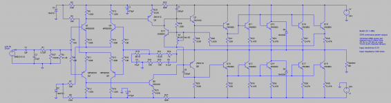
Also, and this really bugs me, is R37 a 1k or 1M resistor. If 1k this will change the input impedance dramatically, and affect the low frequency response. If 1 Meg-ohm then it is totally unnecessary, and can be removed. Also C2 should be around 500 to 680 pF. I'm not certain if yours is a typo, or what is actually installed.
Last comment - my amp has a 1000uF 50V for C3 instead of 470uF. This was evidently done on recommendation from Bedini. Might be worthwhile trying this at some point. I have included the circuit diagram of my Bedini for reference. And this was drawn directly from my amp's PCB by Alan Hobkirk - well known in South Africa for his repair and rebuilding skills.
Kevin
I would replace the 1n4751 zeners with 1n4742. This is in line with the original Bedini design that limited the voltage for the differential pair to 12 V. I had the diff-pair failing a few times because the voltage was too high. I have BC550/560s here because the MPS8xxx series was not readily available here in South Africa. After a lot of searching around and speaking to a few people more recently, another alternative here are the ZTX450/550.
As you pointed out, you have matched these diff-pairs. My Bedini original trafo (E-core) was very definitely wound for 20 Volts. The mains voltage is slightly higher here in Pretoria (235 V) so my secondary rails were at 21.4 volts not connected and 28 V connected to the amp PCBs. From what I can recall (15 years ago) when I tested the output offset it normally measured at roughly 60 mV on each channel.
The one thing I do not see is the two 3 Ampere diodes that are connected from the PSU rails to ground. This was a modification to the original circuit for the 25.25 amp.
Also, and this really bugs me, is R37 a 1k or 1M resistor. If 1k this will change the input impedance dramatically, and affect the low frequency response. If 1 Meg-ohm then it is totally unnecessary, and can be removed. Also C2 should be around 500 to 680 pF. I'm not certain if yours is a typo, or what is actually installed.
Last comment - my amp has a 1000uF 50V for C3 instead of 470uF. This was evidently done on recommendation from Bedini. Might be worthwhile trying this at some point. I have included the circuit diagram of my Bedini for reference. And this was drawn directly from my amp's PCB by Alan Hobkirk - well known in South Africa for his repair and rebuilding skills.
Kevin
Attachments
Last edited:
These Zener diodes have no direct influence on the voltage of the diff pairs.
Instead the tail current is set by these, together with R4 and R7 of post 22.
Of course this will as a result change the collector voltages also.
This will change and may disturb the function of the following stages.
Handle with care.
Instead the tail current is set by these, together with R4 and R7 of post 22.
Of course this will as a result change the collector voltages also.
This will change and may disturb the function of the following stages.
Handle with care.
An Addendum to the 3 Ampere diodes. I missed the 1n4004s (D3 and D4) on your circuit. The originals in my amp were SC10 diodes (600 V @ 3 A types) and were replaced with 1n5405. I'm not certain why such massive ones, but hopefully someone with better electronic knowledge than me will be able to shed some light. All other pictures of Bedini amps similar to yours and mine, appear to also have 3A diodes installed here.
Kevin
Kevin
Hi as_audio,
Thanks for your help. I am not very clued up with electronics. I just based my changing of these on the original Bedini circuit. This definitely shows these as being 12 V zeners, and the dif-pair being MPS8099s and MPS8599s. What would the effect be if using more modern devices like the BC550/560 or the ZTX ones?
Kevin
At low supply voltages as shown I see no obvious differences.
PS to the Zener choice : I referred to schematic in post 22, but
your scheme in post 9 is different.
Using a 12 V Zener in this one means that the output can never
exceed 12 V peak.
I guess that drawing is wrong.
PS to the Zener choice : I referred to schematic in post 22, but
your scheme in post 9 is different.
Using a 12 V Zener in this one means that the output can never
exceed 12 V peak.
I guess that drawing is wrong.
Last edited:
Also, and this really bugs me, is R37 a 1k or 1M resistor. If 1k this will change the input impedance dramatically, and affect the low frequency response. If 1 Meg-ohm then it is totally unnecessary, and can be removed. Also C2 should be around 500 to 680 pF. I'm not certain if yours is a typo, or what is actually installed.
Hi Kevin, I am happy to see you here. Let me first comment on R37. The schematic I posted under #22 shows the Bedini 25 1-MEG (not the 25/25) as far as I can tell in original condition. As the Bedini 25/25 is already relatively well documented, I wanted to see where differences might be between those two. There seem to be quite some strange features and quirks, which I do not understand (with my limited electronics knowledge), one is for sure R37. As you can see on the attached image it shows a resistor value of 1004F (which is 1 M Ohm, as far as I can tell) and the red lines show the traces on the backside. 2742F is the corresponding R2 with 27.4K. This is the amp in the state when I received it. Circuit boards for both channels showed a wild mix of blue Corning Glass Works RN60D resistors and brown Dale RN60D resistors, on both boards for the same values sometimes CGW, sometimes Dale resistors used. Comparing with other images of Bedini amps this seemed to be quite usual. Getting back to the R37 and R2 - these are definitively parallel resistors, their resulting value is approx. 26.67K. In the same way, all other components on the #22 schematic show what I would expect to be the original state of the amp, having already removed obvious later changes. Anyway I cannot guarantee that #22 schematic does not result from changes made many years ago, maybe even by Bedini himself. Therefore I would open this for discussion... Btw. you will also see, that the Zener is a 1N4751, R3/R8 have 5.6K value and you can trust me, that C2 is of 22pF which is very different to what the Bedini 25/25 shows here. Looking forward to your ideas, Markus

Last edited:
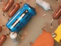
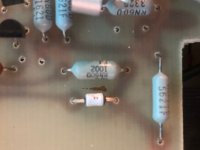
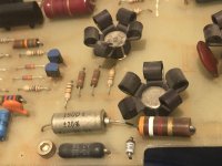
Thank you. So as it looks like the voltage divider at the 45/45 is also setup with a 5K6 resistor and the 1N4751 (30V) z-diode. Can you tell the value of the upright brown Dale resistor? This should be the questionable 1004F. Interesting to see, that the other one is a 26K7, which is the same value as my 27K4 and the 1M0 in parallel. Anyway there is this third one... Also interesting to see the 47uF capacitor. At my 25 1-MEG this has been replaced with a 1000uF at a later time, but I assume the 47uF is also there the intended value.
photos
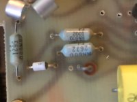
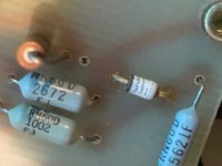
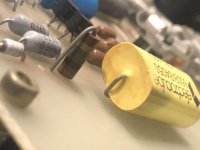
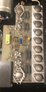
The first two photos are of the 45/45. First of the upright resistor and second is the entire board.
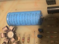
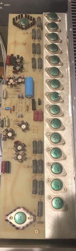
Last three photos are the same areas of the board as I sent from the 45/45 but this time from a "100/100 1 MEG", which might share more parts with your 25/25 1 MEG than the 45/45 does.
The first two photos are of the 45/45. First of the upright resistor and second is the entire board.
Last three photos are the same areas of the board as I sent from the 45/45 but this time from a "100/100 1 MEG", which might share more parts with your 25/25 1 MEG than the 45/45 does.
Attachments
board bedini
Hi gents,
bonsoir
avez vous les fichiers pour réaliser les circuits imprimé
cdlt kriss
Here is the new PCB a friend laid out for me. Slightly larger than the original, but will be going into a custom cabinet in any case. I also have much larger heatsinks, and will be using two LT4320 cap-multiplier power supplies each with its own 160 VA toroidal. The new sinks being 150 mm high have roughly 5 times the radiating area of the originals. I may split them into two separate cabinets to place them just behind the speakers, but then the signal leads would have to be almost 3.5 metres long. I really don't want to build a balanced input circuit for this amp, but may end up doing it in the long run.
P.S. PCB 99% done by my best friend. Just needs the trimpots.
- Home
- Amplifiers
- Solid State
- Bedini amp repair advice