I am not sure if putting the anti-riaa filter AFTER the preamp and RIAA would be "realistic" for calling it somehow. On all reviews measurements I have seen the anti-RIAA is always applied at the preamp input.
For simulating the frequency response with a small-signal (AC) analysis, it doesn't make any difference what the order of the anti-RIAA filter and the preamp is. You simply get the product of the small-signal transfers of the amplifier and the filter and multiplication is commutative (a times b equals b times a).
It does matter when you want to measure rather than simulate the response. For a real measurement, you have to make sure that the signal levels are far enough above the noise and hum levels and still low enough not to cause any clipping. That's easier when the signal first goes through the filter and then through the amplifier.
If you want to simulate distortion over frequency, it can also be handy to have an anti-RIAA filter between the signal source and the amplifier.
Maybe you should either reconsider making an all-in-one testbench or add some switches that can be controlled with parameters.
Of course that in tests they also use an LP with an FR sweep track, incorporating the cartridge and disk surface distortion and noise into the picture. Which is what we are trying to simulate.
Is it? I also like to know the noise with no record playing, but maybe that's because I'm weird. In any case, modelling surface noise and record distortion will again complicate matters.
The usual approach is to determine the noise and distortion of the preamplifier, usually including the cartridge impedance model's thermal noise. When both noise and distortion are negligible compared to the noise and distortion of a new record, you have a pretty good amplifier. When the noise of the amplifier and cartridge is only slightly higher than the thermal noise of the cartridge itself, there is not much point in reducing the noise anymore even when you care about the noise with no record playing.
MarcelvdG is right. New LP releases are growing up, so it doesn't seem just a passing revival.
Working in small signals with inductors for filters doesn't seem like a good thing, particularly if they are not air-cored. So I do no think inductors should be uses in RIAA filters.
Working in small signals with inductors for filters doesn't seem like a good thing, particularly if they are not air-cored. So I do no think inductors should be uses in RIAA filters.
Is it? I also like to know the noise with no record playing, but maybe that's because I'm weird. In any case, modelling surface noise and record distortion will again complicate matters.
The usual approach is to determine the noise and distortion of the preamplifier, usually including the cartridge impedance model's thermal noise. When both noise and distortion are negligible compared to the noise and distortion of a new record, you have a pretty good amplifier. When the noise of the amplifier and cartridge is only slightly higher than the thermal noise of the cartridge itself, there is not much point in reducing the noise anymore even when you care about the noise with no record playing.
Certainly, first of all we have to get to measure the preamplifier noise, and it's where it all started. Then, if it's possible, look for any way to add more variables to the simulation, like a model for the cartridge.
Simulating surface noise is probably impossible, as I think the playing process is greatly non-linear up to a certain point. But I might be wrong and there has been someone who developed such models.
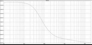
I made some noise simulations, shown above, but I need someone to interpret them for me, which they have such a shape, in frequency and phase.
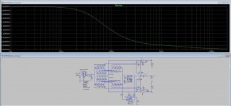
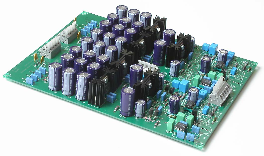
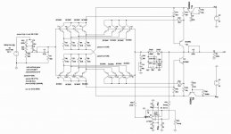
Long time ago I made a pcb for this LT1115 application note.I post all three figures once more
LT1115 Datasheet and Product Info | Analog Devices
Looking at the pcb, you seem to have used the DC-servo version of the LT1115 datasheet. Which is a good thing, if the LTSpice simulations are taken into consideration.
Pity you didn't use a better regulator, at least a Sulzer type, instead of what seems like a simpler 317/1083 type. Or is something else hidden between those capacitors?
Did you measure any THDs or noise on that project?
Pity you didn't use a better regulator, at least a Sulzer type, instead of what seems like a simpler 317/1083 type. Or is something else hidden between those capacitors?
Did you measure any THDs or noise on that project?
Not so convinced passive feedback is a good choice, and neither were the designers of that RIAA preamp.
On these tests, the only passive preamp I simulated was the on the LM4562 datasheet.
The THD results were very poor, compared to those from the SLN and the LT preamp.
Even replacing the LT1115 for the LM4562 gave better results than with the passive RIAA.
Erno Borbely had suggested a good compromise, using two preamp discrete stages. the first passive, the second active.
As the FETs he used are not available anymore, I have been looking for discrete or opamp stage to used to update that design.
Attachments
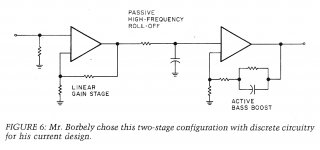
What you mean passive feedback, nonsense. You have passive filtration between two stages, feedback is gain control. First stage is ultra low noise input buffer with appropriate gain (MC/MM), than passive RIAA filtration to ground; next step is stabilizing gain to output with max 100 Ohm impedance to exit. This is approximately lower phase shift possible solution. In opposite case you got maybe better curve, but dead sound. In my neighborhood there are many producers of classic turntables (Kuzma F. /Stabi-Stogi/ 15 miles away; Mezek P. /Pear Audio/ 5 miles away, MAG-LEV Audio 50 miles away) After 40 years’ research, maybe I know something.
Besides my wrong expression, as I meant passive RIAA instead of passive feedback (which doesn't exist), my experience with passive RIAA interstage feedback discrete preamp, resulted in quite an uninteresting sounding preamp. Boring to listen to.
Sorry if I do not agree with your expression that 40 years research make you "know something", as if that something was all there is to it. It maybe a hundred years and still know just part of that something, your version and opinion of things.
Erno Borbely, who also got world respect in the audio circles, certainly had a lot of years, and on his The Audio Amateur article he analyzes all the options, and got to the one I showed as the best compromise. He analyzes every option thoroughly.
When you speak about "dead sound" or things like that, it's just your opinion, not a fact.
My investigation is now in the simulation stage, and then will come the practical stage, where the subjective opinions will come out.
Let me now simulate all the option AD and LT showed on their papers, and see what I get.
Last edited:
I'm quite sure you know everything.After 40 years’ research, maybe I know something.
Best regards!
When you speak about "dead sound" or things like that, it's just your opinion, not a fact.
True for all subjective (anyone's) opinions, no simulation will show you "dead sound" as an output parameter.
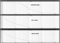
These are the noise curves I got from the SLN and from the opamp+buffer preamps.
The second and third plots indeed look suspiciously similar, although there appears to be some difference at higher frequencies. In fact the AD745 amplifier appears to be slightly worse than the LF411 amplifier at 1 kHz, which doesn't make any sense at all when the gains are similar. An AD745 produces 3.2 nV/sqrt(Hz) of noise at 1 kHz, while an LF411 produces 18 nV/sqrt(Hz), both with negligible noise current.
Could you plot the graphs with logarithmic Y-axes and check what the gains are at 1 kHz?
Did you look at the schematic IRIAA as source with a high enough resistance level there the op-amps will make no difference? A lot going on wrong here.An AD745 produces 3.2 nV/sqrt(Hz) of noise at 1 kHz, while an LF411 produces 18 nV/sqrt(Hz), both with negligible noise current.
I thought the output resistance of the inverse RIAA filter was <= 604 ohm, or was that a different version?
Sorry I can't read the schematic enough to tell what the resistive part is at @1k.
- Status
- This old topic is closed. If you want to reopen this topic, contact a moderator using the "Report Post" button.
- Home
- Source & Line
- Analogue Source
- BC550 BC560 Very low noise RIAA