It is from Wireless World, March 1983, Pages 69-75.
Sigurd
Sigurd
janneman said:If it is an Audio Amateur article I have it. Do you know year, issue?
Jan Didden
I've seen that WW paper and it is something of a puzzle.
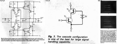
Erno shows in one figure the composite "Hawksford-style" cascode as a "floating" circuit with a battery and two transistors. The output collector is labeled C, the input base B, and the bottom emitter and end of battery E. Then as Walt mentions, he shows the improved performance of cascode versus non-cascode. But he does not show the overall circuit upon which the curve tracer photos are based.
Then he builds his driver stage and then complete power amplifier, and the outputs of conventional two-Q emitter-ballasted darlingtons are cascaded into common-base stages, but with the CB bases referenced via diodes to the rails, NOT to the darlington emitter R's.
So this leads one to suppose that he did not have Hawksford-style enhancement in mind to begin with.
Brad
Erno shows in one figure the composite "Hawksford-style" cascode as a "floating" circuit with a battery and two transistors. The output collector is labeled C, the input base B, and the bottom emitter and end of battery E. Then as Walt mentions, he shows the improved performance of cascode versus non-cascode. But he does not show the overall circuit upon which the curve tracer photos are based.
Erno's use of the driven cascode predates Hawksford, by 5 years. Strange that Hawksford wouldn't have referenced Erno, but who knows? Plus, it may be confusing to some read about a "Hawksford-style enhancement", that, in 1983, had not yet appeared.
Let's give Erno the credit due for establishing the point through graphical measurements that this type of cascode does indeed lower distortion.... even if it didn't get used in his final implementation of the PL and PCB.
wj
Well, as Hawksford apparently missed Baxandall, he could surely have missed Borbely! But I agree with your point Walt---the reason I said "Hawksford-style" in quotes goes back to an earlier post in this thread, where his priority was indeed questioned, but the utility of calling it by his name, in light of his lengthy AES paper, was proposed.
I would also point out, taking nothing away from Erno's application to audio circuits, that many had used the cascode (and even as the sort-of driven cascode in composite JFET parts, as mentioned by Pass earlier in the thread) and recognized the improvement in output impedance, and hence circuit linearity, among other benefits, still well before 1983 (wish I could easily document this assertion!).* But it was good for Erno to show curves---though again we don't know if they were of the specifically driven cascode.
Brad
*In fact I recall I think that Nelson Pass used a cascode output stage (don't know the circuit, just remember the promotion) in an audio power amp once or twice, I think before the days of Stasis (?) and when he and a friend (Nelson, do you remember Teddy Tech? Some Jerry something guy?) were pitching a home audio/video switcher to my late father's company, I mentioned that the design was maybe not easy to protect, that a lot of people tend to get the same ideas around the same time, and that I had used a cascode (not driven though) output stage for a vidicon deflection coil driver back around 1973, having not seen it before---but hardly thought anyone had stolen the idea when I saw it used elsewhere later on")
I would also point out, taking nothing away from Erno's application to audio circuits, that many had used the cascode (and even as the sort-of driven cascode in composite JFET parts, as mentioned by Pass earlier in the thread) and recognized the improvement in output impedance, and hence circuit linearity, among other benefits, still well before 1983 (wish I could easily document this assertion!).* But it was good for Erno to show curves---though again we don't know if they were of the specifically driven cascode.
Brad
*In fact I recall I think that Nelson Pass used a cascode output stage (don't know the circuit, just remember the promotion) in an audio power amp once or twice, I think before the days of Stasis (?) and when he and a friend (Nelson, do you remember Teddy Tech? Some Jerry something guy?) were pitching a home audio/video switcher to my late father's company, I mentioned that the design was maybe not easy to protect, that a lot of people tend to get the same ideas around the same time, and that I had used a cascode (not driven though) output stage for a vidicon deflection coil driver back around 1973, having not seen it before---but hardly thought anyone had stolen the idea when I saw it used elsewhere later on
My interpretation of what Erno tested for the curves of Fig. 8b is a composite as per his Fig. 7. This what we have been discussing.
Nelson Pass said earlier that cascodes such as this have been around for some time, and I'd echo that. They are treated within Evans' book in a small signal context: Arthur D. Evans, Designing With Field-Effect Transistors, McGraw-Hill, ISBN 0-07-057449-9, 1981. This book references original work by Jim Sherwin, which goes back to the 1970's.
Which brings us back to the germane question, when was such a cascode, shown to be superior for large signal audio power amp applications, first used as such? Perhaps Nelson Pass could help here, I don't know without some research.
Walt Jung
I guess the question still in my mind is---does figure 7 imply that the "E" of the composite device is working in a circuit that has at least some impedance in that composite emitter? Since when "applied" in the amplifier schematics we see only the standard cascode, with no second device feedback a la Baxandall and variants, I wonder.
After all, the two sets of curves could be generated with no impedance in the emitter, and still show the improvement as documented in the scope photos.
Erno where are you??
After all, the two sets of curves could be generated with no impedance in the emitter, and still show the improvement as documented in the scope photos.
Erno where are you??
Aha.
Found a diagram in Cobbold, Theory and Applications of Field-Effect Transistors, published in 1970; on page 379 there is Figure 10.15, "Compound current source" which has the gate of the second device tied back to the source of the first, with an "Rs" in the source to one of the two terminals. A low-frequency analysis is given in the text.
However, no discussion is made of the effect on output capacitance of the (partial) feedback of second-device drain-gate capacitance displacement current to the first-device source.
Cobbold shows the circuit without attribution.
bcarso said:[snip]Erno where are you??
I'm pretty sure he is listening...
Jan Didden
I have now studied the article, and see no puzzle. Instead I see that Borbely in fig 7 shows a driven cascode and in fig 8 shows how linear this cascode becomes.
However, in his final power amplifier design, Borbely does not use a driven cascode but a normal telescopic cascode referenced to GND.
Attached are the three figures.
Sigurd
However, in his final power amplifier design, Borbely does not use a driven cascode but a normal telescopic cascode referenced to GND.
Attached are the three figures.
Sigurd
bcarso said:I've seen that WW paper and it is something of a puzzle.
Erno shows in one figure the composite "Hawksford-style" cascode as a "floating" circuit with a battery and two transistors. The output collector is labeled C, the input base B, and the bottom emitter and end of battery E. Then as Walt mentions, he shows the improved performance of cascode versus non-cascode. But he does not show the overall circuit upon which the curve tracer photos are based.
Then he builds his driver stage and then complete power amplifier, and the outputs of conventional two-Q emitter-ballasted darlingtons are cascaded into common-base stages, but with the CB bases referenced via diodes to the rails, NOT to the darlington emitter R's.
So this leads one to suppose that he did not have Hawksford-style enhancement in mind to begin with.
Brad
Attachments
But...with no load or reference shown for the composite emitter in Fig. 7---that could still be thought of as referenced to common, rather than some resistance to common (or supply rail).
If no resistor, no driven cascode. Not clear to me anyway (as one guy I know would say at that statement, "That's easy for you to say").
If no resistor, no driven cascode. Not clear to me anyway (as one guy I know would say at that statement, "That's easy for you to say").
More Baxandall et al References
Some References Related to the Larson, Baxandall / Swallow, and Thompson Constant Current Circuits:
In an earlier post to this “Baxandall Super Pair” thread, I offered a list of references. The updated list below expands on this with several key items. Some comments on the first few of these follow, and these will greatly help in understanding this clever circuit..
In #1, Larson provides an analysis on the use of a composite PNP/NPN complementary pair as a functional high-gain NPN, with two such pairs operated differentially. The impedance characteristics of the output stage device is seen to be improved by a factor of b, the gain of the driving transistor.
In #2, Baxandall and Swallow discuss a (single) current source stage of the PNP/NPN type, having similar improvements with regard to output impedance.
In #3, Jim Thompson describes an op amp with a Figure 6 NPN/PNP current source, designed to overcome the PNP IC transistor b limitations. This NPN/PNP configuration is a functional complement akin to ½ the Larson and to the Baxandall-Swallow setups. It was to be used many times over in other Motorola ICs of the period, in addition to discrete examples within applications.
In #4, Jim Solomon offers a detailed analysis on the use of a composite complementary NPN/PNP pair ala Thompson (above), as a functional high-gain PNP pair, within the front end of what became the MC1556 IC op amp.
In #5, Tom Frederiksen describes use of the Thompson composite complementary pair within a high powered voltage regulator IC.
In #6 the Thompson composite complementary pair is used in Figures 9 and 10 as a current mirror employing 2N3904/3906 discrete transistors. In #7 the Thompson composite complementary pair is used in Figures 3 and 4 as a current mirror employing 2N3904/3906 discrete transistors.
In #8, Maurice Free describes the MC1595 multiplier design, which uses externally the Thompson current source scheme, within an output stage current mirror (Figs. 3 and 4).
My thanks to Jim Thompson for help with his MSEE thesis (#3), and to Maurice Free for help with his MSEE thesis (#8). Thanks also to an anonymous friend for providing the Larson reference, and to Ben Duncan and Morgan Jones, who also provided several references and other background information. Bob Pease has also related his independent development of this type of circuit, in #15 and 17.
Walt Jung
Rev L 032509
1. L. L. Larson, “Differential Amplifier Having Common Base Output Stage of Very High Impedance”, US Patent 3,394,316, filed Jan 29, 1965, issued July 23, 1968.
2. P. J. Baxandall, E.W. Swallow, “Constant Current Source With Unusually High Internal Resistance And Good Temperature Stability,” Electronic Letters, Sept. 1966, Vol. 2, No. 9, pp. 351-352.
3. James Elbert Thompson, “A High Performance Operational Amplifier Utilizing Field Effect Input Devices Compatible With Integrated Circuit Fabrication Techniques”, MSEE Thesis, Arizona State University, June, 1968. See also http://analog-innovations.com/MS_Thesis_JE_Thompson_1968.pdf
4. J. E. Solomon, “Lateral PNP-NPN Composite Monolithic Differential Amplifier”, US Patent 3,538,449, filed Nov 22, 1968, issued Nov 3, 1970.
5. Thomas M. Frederiksen, “A Monolithic High-Power Series Voltage Regulator,” IEEE Journal of Solid-State Circuits, Dec 1968, Vol. 3, #4, pp. 380–387.
6. Ed Renschler, “Analysis and Basic Operation of the MC1595,” Motorola Semiconductor Products, Multiplier Series Part I, Application Note AN489, September 1969.
7. Brent Welling and Loren Kinsey, “Using the MC1495 Multiplier in Arithmetic Operations,” Motorola Semiconductor Products, Multiplier Series Part II, Application Note AN490, September 1969.
8. Maurice George Free, “An Integrated Linear-Transconductance Analog Multiplier”, MSEE Thesis, University of Arizona, 1970. See also “An Integrated Linear-Transconductance Analog Multiplier”, Simulation, Vol. 13, #5, November 1969, pp. 243-251.
9. “MC1594L/MC1494L Data Sheet, Figure 15,” Motorola Semiconductor Products, October 1970.
10. Allan Grebene, section 4-5, pp. 133-136, 143-144, within Analog IC Circuit Design, Van Nostrand Reinhold, 1972, ISBN 0-442-22827-9.
11. Hans R. Camenzind, ‘Voltage-to-Current Converter’ section, pp. 266-269, within Chapter 16 ‘Linear Elements, Circuits, and Subsystems’ of Electronic Integrated Systems Design, Van Nostrand Reinhold, 1972.
12. R.C. Jaeger, “A High Output Resistance Current Source,” IEEE Journal of Solid-State Circuits, Aug 1974, Vol. 9, # 4, pp. 192–194.
13. B. Hart, “Homage To Baxandall,” Electronics World (Letters), Jan. 2003, pp. 41.
14. N. Terzopoulos, K. Hayatleh, B. Hart, F. J. Lidgey and C. McLeod, “A Novel Bipolar-Drive Circuit for Medical Applications,” Physiological Measurement Journal, Issue 5, N21-N27, October 2005.
15. Bob Pease, “What's All This PNP Stuff, Anyhow?,” Electronic Design, Sept. 11, 2008, pp. 80. See also http://electronicdesign.com/Articles/ArticleID/19605/19605.html
16. Dimitri Danyuk, “On the Optimization of Enhanced Cascode,” Preprint #7571, Presented at the 125th AES Convention, October 2–5, 2008 San Francisco, CA, USA.
17. Bob Pease, “Mailbag; letters from Walt Jung and James E. Thompson”, Electronic Design, October 23, 2008, pp. 72. See also http://electronicdesign.com/Articles/Index.cfm?AD=1&ArticleID=19868
Re: More Baxandall et al References
WaltJ:
thanks for the updates!
mlloyd1
WaltJ:
thanks for the updates!
mlloyd1
WaltJ said:Some References Related to the Larson, Baxandall / Swallow, and Thompson Constant Current Circuits
...
Walt Jung
Rev L 032509
Sure thing. But, as noted, I had some help.
wj
wj
WaltJ: thanks for the updates! mlloyd1
Thnx Bob for saying that. But as I said earlier, I did have some good help.
Bob Cordell said:That's a great set of references, Walt. Thanks!
Best,
Bob
Does anyone know what the earliest occurrence of the Baxandall super-pair was? One presumes it was in something of Peter B.'s...
"
The term "Baxandall Super Pair" is complete new for me, and I am not a beginner. Unfortunately, I also don't find more informations in the web about this. Only the following articles from Baxandall are provided as references:
1. P.J. Baxandall, E.W. Swallow, “Constant Current Source With Unusually High Internal Resistance And Good Temperature Stability,” Electronic Letters, Sept. 1966, Vol. 2, No. 9, p. 351-352.
2. P.J. Baxandall P. Baxandall, "Negative Feedback Tone Control" (Independent Variation of Bass and Treble Without Switches), Wireless World, Oct. 1952, pp. 402-405.
3. P.J. Baxandall "Electrostatic loudspeakers", in "Loudspeaker and Headphone Handbook" 2nd Ed., J.Borwick, Ed. (Butterworths, London, 1994).
4. P.J. Baxandall "A Technique for Displaying the Current and Voltage Output Capability of Amplifiers and Relating This to the Demands of Loudspeakers" presented at the 82nd Convention of the Audio Engineering Society (1987 March). Preprint 2421. J. Aud. Eng. Soc. Vol.36, p.3 (1988 January/February).
and here in the forum:
http://www.diyaudio.com/forums/solid-state/13590-psrr-topologies-device-characteristics.html
Perhaps the term "Baxandall Super Pair" was coined in this forum? If so, why this name?
Last edited:
Tiefbassuebertr, the 1965 Larson filing and the 1966 Sept. I source article by Baxandall and Swallow seem to be the earliest descriptions of the topology. I am not sure who started to call it the Baxandall super-pair, but I am pretty sure it predates this forum. Walt's bibliography earlier in this thread is the most complete that exists and is probably comprehensive.
Why the name (regardless of whoever coined)? Well---it has wonderful properties! Try to get high output Z from d.c. to moderately high frequencies in other ways, and its benefits become obvious. It was part of an effort to develop such that led me to the circuit. And don't feel bad that the term is new to you. I'm not a beginner either, and it was the devil to find. Turned out (thanks again Walt) it lurked in an old book I have of Grebene's (see ref. above), shown as a strategy for improving the output impedance of lateral PNPs in early ICs, so I must have seen it ages ago.
Brad
Last edited:
Tiefbassuebertr, the 1965 Larson filing and the 1966 Sept. I source article by Baxandall and Swallow seem to be the earliest descriptions of the topology. I am not sure who started to call it the Baxandall super-pair, but I am pretty sure it predates this forum. Walt's bibliography earlier in this thread is the most complete that exists and is probably comprehensive.
Why the name (regardless of whoever coined)? Well---it has wonderful properties! Try to get high output Z from d.c. to moderately high frequencies in other ways, and its benefits become obvious. It was part of an effort to develop such that led me to the circuit. And don't feel bad that the term is new to you. I'm not a beginner either, and it was the devil to find. Turned out (thanks again Walt) it lurked in an old book I have of Grebene's (see ref. above), shown as a strategy for improving the output impedance of lateral PNPs in early ICs, so I must have seen it ages ago.
Brad
I remember a very early article from Baxandall where he showed this 'super pair' but named it 'the Liniac' for linear AC amplifier. I think it was in Wireless World.
jd
jd, you may be recalling John Linsley Hood's article in WW about integrated Darlingtons, his point being that the IC realization allowed appropriately smaller geometry transistors for the input device. This is not the super-pair topology, and having seen the original article recently I don't recall it there.
See for example: A Paul Kemble web page - John Linsley Hood preamp designs.
Brad
See for example: A Paul Kemble web page - John Linsley Hood preamp designs.
Brad
- Status
- This old topic is closed. If you want to reopen this topic, contact a moderator using the "Report Post" button.
- Home
- Amplifiers
- Solid State
- Baxandall Super Pair