modified my design just for fun.
I have an esp p88 pre with both side ground planes, it doesn't hum in an integrated amp which also has protection and led vu meter circuitry.
I have an esp p88 pre with both side ground planes, it doesn't hum in an integrated amp which also has protection and led vu meter circuitry.
Attachments
1) Eliminated feedback resistors as per Resistors in the feedback of a buffer: Ask why! - Precision Hub - Archives - TI E2E support forums
View attachment 979690
Very interesting! However contrary to what is claimed
. However, as my now-retired colleague Bruce Trump pointed out in an article on input bias current cancellation resistors, this is rarely effective.
in my designs this resistor is very effective. I have built buffers with the 5532 (high input bias current) with 0.2 mV or less DC offset. Furthermore, if DC offset can't be made practically zero, this resistor can greatly mitigate the DC offset (or limit it to a manageable range in circuits with variable resistors).
As far as the analysis of the phase response, very interesting and easily mitigated with a small ceramic capacitor. In a lot of audio circuits that employ "slower" op amps, it is of no consequence at all.
As I understand it, in a Baxandall volume control the absolute value of the controls does not need to be matched. It is the control law, the slope, that needs to be matched and it is much better in a dual control than the absolute value.
One of the reasons why the Baxandall volume control used to be so popular.
Jan
One of the reasons why the Baxandall volume control used to be so popular.
Jan
..... why the Baxandall volume control used to be so popular.
Was it? I have only seen it in niches.
The Bax TONE control was universal, in part because dual linear pots usually ratio-track OK naturally, and pot-value matching is not very critical.
modified my design just for fun.
I have an esp p88 pre with both side ground planes, it doesn't hum in an integrated amp which also has protection and led vu meter circuitry.
Nice
")
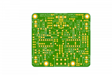
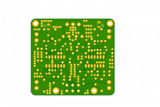
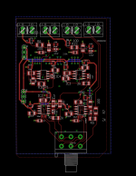
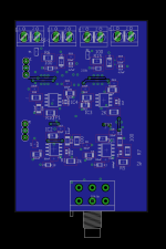
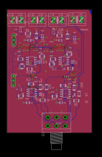
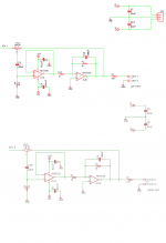
After many delays, i finished my board, ready to be sent. This is my first SMD board and I have incorporated all the ideas layout I have read around about audio. I tried to keep the bottom as solid as I could, avoid islands and use stitching to maintain the integrity of the bottom layer. The circuit has been designed and routed in blocks so I can cut and paste and/or extend the board (more channels, some extra functionality between the input and filtering and the volume controls). It will be also my first jlpcb experience, so I they are going to fab and populate the boards. I used what they had, and as opamps I choose ne5532 as it was what they had available. The schematic, basically the reference design with a different opamps. Just have to doublecheck the part numbers on the bom and I will be ready to submit. The only thing I am not sure at this point is if the components need some adjusting due to the change of opamps.
Attachments
Last edited:
- Home
- Source & Line
- Analog Line Level
- Baxandall gain control according TI tidu34 certified design