You will notice that there is no feedback on the op-amp. You are using its gain so that it acts like a schottky gate. There will be no gradual dimming of the LED, as soon as the inverting input drops below the threshold voltage the LED will come hard on.
The transistor is nothing special, by inverting the circuit you could even use a PNP.
I guess that several guys will suggest improvements but this is really basic and will do the job. You could use a zener in place of the bottom resistor of the reference divider but as its being fed with a regulated supply it isn't really necessary.
The whole circuit will draw about 1-2 mA until the LED illuminates, then the current is largely through the LED. You could increase the 470R LED resistor but that depends on the LED that you use. R = Vcc - Vf - Vce / If. So Vcc = 5V, Vf with a red LED is about 1.8V, Vce will be about 1.2V. If the LED will work with If = 5mA, R needs to be ~ 400R.
Last edited:
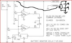
Thank you guys for all your help & suggestions. I've just tried the circuit I have on a breadboard & it works. I'm using 5k trimmers after setting the range at 1k on both. The "Green" led lights up since the voltage is 14.7v with 4 batteries. The Red lights up on 3 batteries with the voltage @ 11.1v. The only problem is setting these levels properly for the lack of a variable dc supply!
I need to fine tune these to;
Over 12.0v= Green
Between 11.9 - 11.5 Yellow (both leds on)
Below 11.5 Red
Any workabouts around fixed voltages?
Can any one suggest a low current bi-color (green/red) 3mm LED if such exists?
Thanks
I need to fine tune these to;
Over 12.0v= Green
Between 11.9 - 11.5 Yellow (both leds on)
Below 11.5 Red
Any workabouts around fixed voltages?
Can any one suggest a low current bi-color (green/red) 3mm LED if such exists?
Thanks
"Any workabouts around fixed voltages?"
You mean the circuit in post #11 ?
Use two 9 volt batteries in series and a pot to feed just the resistor chains. Use something like a 2K2 preset and work your way through the voltage range. Keep the main circuit powered up from the normal supply.
Edit... you connect the pot across the batteries and take the output from the wiper.
"Any workabouts around fixed voltages?"
You mean the circuit in post #11 ?
Use two 9 volt batteries in series and a pot to feed just the resistor chains. Use something like a 2K2 preset and work your way through the voltage range. Keep the main circuit powered up from the normal supply.
QUOTE]
Yes!...I'm not sure if I understood your 1st sentence! Perhaps a sketch if possible? A "pot" connected to the main batt. as you've suggested looks less complicated. Shuldn't this then be adjusted with the load connected,as no load settings wouldn't be the same as under load?
K&D, thanks, Yes they are a plenty,yet haven't come across any bi-colour LEDs under If of 20mA! not sure if these are rated @ If/led? or 40mA total? I'm looking for one under 5mA-10mA rating! A super bright led with a higher value resistor perhaps?
For Li Ion batteries you also need to be very cautious about charging them. So while the discussion has been about low voltage monitoring, you should also think about how these will be charged. Overcharging of Li ion batteries is very bad for them.
If you have a separate charger then all is fine, but if you want to charge in situ, then you really must include an over-voltage sense and ideally cutout. The circuit would actually be very similar to the ones presented to date, but with the comparator "flipped over".
If you have a separate charger then all is fine, but if you want to charge in situ, then you really must include an over-voltage sense and ideally cutout. The circuit would actually be very similar to the ones presented to date, but with the comparator "flipped over".
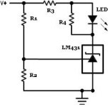
The Regulator here is only a voltage reference. Its a little more accurate than a zener, but still, a 7805 is not really suitable in this circuit. Many of these types need a minimum output current for stability, and this is something you do not want eating your batteries.
A simple TL431 will do, Also try here: Maxim - Parametric Search - Product Table
A simple TL431 will do, Also try here: Maxim - Parametric Search - Product Table
My main concern is battery drain! As I understand it, reducing brightness/current with a higher value R is still a waste as it only just dissipates as heat in the resistor correct?, defeating the whole purpose of the exercise i.m.h.o....or am I way out here?
Thanks Mooly for the sketch...it made it all the more clearer!
Yes, I'm quite aware of the perils of using Li-ions...however,these will go through a 4S PCM card which has both cell balance & maximum charge/discharge threshold! Very handy indeed. I will be incorporating a switch too for selecting between charging/discharging.
I did look at many TL431 battery monitor circuits, but with just 1 LED; besides many DIYers have claimed that it doesn't work properly! I once came across a schematic which used 2 LEDs, but unable to find it now!
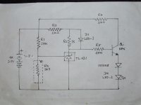
Is there anything wrong with my current schematic? I wll be certainly replacing 7805 with LP2954 regulator! Can anyone suggest a better opamp than LM358 for this if this will improve it?
Thanks Mooly for the sketch...it made it all the more clearer!
Yes, I'm quite aware of the perils of using Li-ions...however,these will go through a 4S PCM card which has both cell balance & maximum charge/discharge threshold! Very handy indeed. I will be incorporating a switch too for selecting between charging/discharging.
I did look at many TL431 battery monitor circuits, but with just 1 LED; besides many DIYers have claimed that it doesn't work properly! I once came across a schematic which used 2 LEDs, but unable to find it now!
Is there anything wrong with my current schematic? I wll be certainly replacing 7805 with LP2954 regulator! Can anyone suggest a better opamp than LM358 for this if this will improve it?
Attachments
Last edited:
...
Can anyone suggest a better opamp than LM358 for this if this will improve it?
Look for micro power op-amps...designed specifically for battery operation.
In Digikey search, select the operating current and input current as very low values.
No, not the whole purpose of the exercise.My main concern is battery drain! As I understand it, reducing brightness/current with a higher value R is still a waste as it only just dissipates as heat in the resistor correct?, defeating the whole purpose of the exercise i.m.h.o....or am I way out here?
The LED will have a virtually constant Vf across it. The remaining voltage will be dropped across the resistor (independent of resistor value).
Since the voltage across the resistor will also be virtually constant, will more power be wasted with 20mA through the resistor, or with 5mA through the resistor? The obvious answer is a 75% reduction @ 5mA.
You can reduce current consumption by going for a micro power opamp although apart from the old TL062 (around 400uA) I can't offhand quote any later devices. Are there such things has ultra bright bi-colour LED's ? Ideally you want something bright that uses under 1ma, something single colour LED's easily achieve but again they are not something I have needed so not sure what is available. Use a FET opamp (such as the TL062) and increase the resistor network by a factor of 10 or 100 (use multiturn presets for setting accuracy). Use a dedicated micropower voltage reference IC.
Have you considered something like this .... http://docs-europe.electrocomponents.com/webdocs/002d/0900766b8002dbbf.pdf ... It only draws 150uA. Or use a micropower PIC. Or a bit cheaper ... http://www.ebay.co.uk/itm/Blue-LCD-...uipment_ET&hash=item4aba41867e#ht_3986wt_1170
Last edited:
The majority of the current is that taken by the LED. Get the LED current down to 1ma and then swapping the opamp from say a TL072 to a TL062 makes a big difference.
Designing for micropower operation can be fun but you need the right parts. Running the LED's from a low duty cycle oscillator could further push the current down while still maintaining a reasonable brightness but as ever, circuit complexity becomes an issue.
Designing for micropower operation can be fun but you need the right parts. Running the LED's from a low duty cycle oscillator could further push the current down while still maintaining a reasonable brightness but as ever, circuit complexity becomes an issue.
I'm sure it's been voiced already but why not have a separate LED supply. The op-amp surveying the battery need only take uA from the battery, when the LEDs turn on they can draw their power from an auxiliary supply.
As Mooly is intimating, if the surveying circuit is too high impedance you may get incorrect triggering due to noise. 1mA from the main battery is not going to harm it, nor make too much difference to your required results.
As Mooly is intimating, if the surveying circuit is too high impedance you may get incorrect triggering due to noise. 1mA from the main battery is not going to harm it, nor make too much difference to your required results.
Last edited:
- Status
- This old topic is closed. If you want to reopen this topic, contact a moderator using the "Report Post" button.
- Home
- Amplifiers
- Power Supplies
- BATTERY LEVEL MONITOR