I am not familiar with your particular transformer, but...
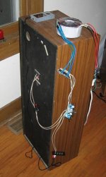
For 115vac mains, aren't the primaries supposed to be wired in parallel? i.e. Shouldn't both red wires be connected to fuse/Hot and both black wires connected to neutral?
For the "universal" (i.e. 115v/230v) dual-primary/dual-secondary transformers that I use, that's how it is usually done. Otherwise, you will end up with half of 115vac across each primary. And I noticed that you labeled each primary with "115v".
If I am right, then if you had 230vac mains voltage, you would wire it as you have shown and would then still end up with 115vac across each primary, which seems to make sense.
In some of the other types of equipment I build, I use a high-current DPDT slide switch for the mains, so that the power supply can be set to run from either 115vac or 230vac.
- Tom Gootee
gootee said:For 115vac mains, aren't the primaries supposed to be wired in parallel? i.e. Shouldn't both red wires be connected to fuse/Hot and both black wires connected to neutral?
Good catch Tom.
The transformer primary windings should indeed be in parallel for 120VAC operation - meaning tie the two red wires together and connect them to 120VAC then tie the two black wires together and connect them to neutral.
Nordic said:Sweet, glad you got it right...
Now remember to look through other builds here for safety tips etc...
Right, as it sat in that picture it was frighteningly unsafe. I should have made it more apparent that I am working on a proper enclosure (mainly to stop clumsey college housemates from face-planting into 120AC
 ). Also, the FM station that it (magically?!) picks up due to a lack of shielding plays awful top40. And that is simply no good.
bcdzt5 said:
Right, as it sat in that picture it was frighteningly unsafe. I should have made it more apparent that I am working on a proper enclosure (mainly to stop clumsey college housemates from face-planting into 120AC
Congratulations! I'm really glad to hear that you got it going, apparently with a minimum of anomalies. Good work.
Are you sure it was an FM station, and not AM? Accidentally making an FM demodulator seems like it would be a LOT harder than just rectifying (and filtering) to demodulate AM, which almost any semiconductor junction can do pretty well; for example, the ones inside opamp and chipamp inputs, and everywhere else! :-o . [If it WAS really FM, I wonder if it could have somehow gotten into your amp AFTER it was demodulated; maybe through the AC power or ground wiring, via someone's tuner's amplifier that has a wiring fault of some sort? Just wildly speculating... Hard to imagine...]
Even if it turns out to be AM, it must be a strong radio station, if you can actually hear the audio. Lesser RF infiltration problems might only result in things like "minor" DC offsets (possibly even internal to a chip), which might be basically "un-noticeable", but could unbalance or otherwise degrade the performance of whatever circuits or devices contain the semiconductor junctions that are involved. Quite insidious, eh? For the highest-quality system, RF should always be filtered out, as much as possible/practical.
Your particular RFI (Radio-Frequency Interference) problem might get a lot better, as soon as you can shorten all of those antenna wires
") , i.e. after you get everything closer together, in a case, with all of the leads as short as possible. And a metal or shielded case should help, too.
, i.e. after you get everything closer together, in a case, with all of the leads as short as possible. And a metal or shielded case should help, too.However, (if) "in case" the problem remains, I like to try an actual RF lowpass filter before resorting to sticking a capacitor across the input pins. (I forget exactly how I arrived at that preference. Maybe someone who has done the math more recently, or is not as lazy as I am, could enlighten us. I could be wrong, too.)
I don't consider myself to be a real expert on this stuff. But I might as well give a "long-form" explanation of simplified RF input filter implementation for opamps and chipamps, for future reference, since, in my opinion, it's quite important to always have such filtering.
(I hope that someone else will jump in, here, if I get something wrong, or if something could use clarifying or expanding.)
For reasons already hinted at, and even if you can't directly hear any interference, "technically", you "should" install an RF filter at every opamp and chipamp "input", which, by the way, also includes the power supply pins and the output pin, as well as every other internally-connected pin.
But, the power supply pins are usually partially taken care of, already, by the decoupling caps and maybe the impedance of the wires or traces leading to them (although a small series resistor, near the decoupling cap(s), can be a good idea, too, to enhance the lowpass behavior, among other things). And the power and output pins "usually" just aren't as susceptible to being complicit in problems caused by RF. So that leaves just the two main signal input pins to worry about the most, most of the time (or at least first). And, in a typical non-differential audio circuit, usually the one input that is getting the actual signal has a lot more conductor-length connected to it than the other input does, and sometimes is tied to an external input. So the signal-input pins are probably the main ones to worry about, first, for RF filtering.
For a NON-INVERTING opamp or chipamp signal-input pin, a resistor in series with the input, with a capacitor from the downstream side of the resistor to ground (i.e. the cap goes from the + input to ground), can form an effective, simple, passive RC lowpass filter. Note that the resistor's value should be kept low, so that it doesn't create much of an offset problem due to the input's tiny current. And the resistor should be close to the input pin. (Of course, if there is already a resistor that happens to be there, you can usually just add the proper cap value to ground.)
So, you can pick any R (probably 50 Ohms <= R <= 500 Ohms would be fine), and also pick a low-pass RF filter cutoff frequency, and then calculate the required C value by rearranging f=1/2/Pi/R/C; i.e. C=1/2/Pi/R/f . I usually never set f very much below about 300 kHz, so I can keep the filter's cutoff frequency a little more than 10x away from 20 kHz (to avoid, as much as possible, affecting the system's frequency response), unless there's some compelling reason for making it lower.
So, for example, if we want R=220 Ohms and f=300 kHz, then we get C=0.000000002 Farads = 2 nF = 2000 pF. The exact value is usually not at all critical. A ceramic capacitor will work extremely well, in this role, by the way.
Note that if you express the frequency in MHz (i.e. 10^6 Hz), not only will your calculator not underflow and cut off some significant figures, the resulting C value will also be in uF (microFarads; 10^-6 F). So, trying that again, 1/(2xPix0.3x220) = around 0.0024 uF = 2.4 nF = 2400 pF.
While small-enough, that C value is a bit larger than I'd hoped. We could approximately double the R and halve the C to get it close to 1000pF (0.001uF), a common value. On the other hand, if you happen to have some 0.01 uF (10nF) ceramics lying around, 51 Ohms or so might work even better.
INVERTING INPUTS are a different story! Placing a capacitance to ground from an inverting opamp input is almost always "a bad thing", and typically causes massive oscillation at the amplifier's output.
Luckily, it's usually very easy to get around that constraint: The trick is to isolate the input from the capacitance, by putting another resistor in series with the inverting input, i.e. between the cap and the input.
If you've already worked out the math for a simple "one R and one C" RC lowpass filter, like in the non-inverting case above, then for the inverting case you can just change the series input resistor into two resistors in series, each with half of the original value, and then connect a cap to ground, from _between_ the two resistors, that has twice the original C value. (You can always scale the R and C values, too, as long as the R x C multiplication product stays about the same.)
(Aside: ) Note that that RCR lowpass configuration also has the advantage of being bi-directional, such that any RF that is trying to sneak around the feedback path, from the output side, will be filtered as it tries to find its way into the input conductor. (Note, too, that if you are filtering both inputs of an opamp or chipamp, possibly for a differential amplifier, you should use RCR for both inputs, and use exactly the same RCR values for both inputs, to keep all impedances matched as well as possible.)
I'm not sure how to know, in advance, how low the "isolating" resistor's value can go, without problems. So you might have to experiment (with speakers disconnected I hope). As a guess, I think that 200 Ohms or so should almost always be safe. (But, as always, "Your mileage may vary.")
That's all, for now. I hope that the fear of even subtle detrimental effects from insidious RF intrusion will motivate more people to always use proper RF filtering.
- Tom Gootee
http://www.fullnet.com/~tomg/index.html
Gootee,
You are right, it only makes sense for it to be AM. I agree that the AM interference will likely be silenced with the addition of an enclosure, and shorter leads (also an AC power filter). If not, I have your post for help, thanks.
I have to admit that I was shocked to hear my amp playing a very tinny rendition of Photograph by Nickel Back before I hooked up any input. This is not the first band I wanted my amp to play . So I guess the lesson is; ground properly, or listen to massively-overplayed alternative rock.
You are right, it only makes sense for it to be AM. I agree that the AM interference will likely be silenced with the addition of an enclosure, and shorter leads (also an AC power filter). If not, I have your post for help, thanks.
I have to admit that I was shocked to hear my amp playing a very tinny rendition of Photograph by Nickel Back before I hooked up any input. This is not the first band I wanted my amp to play
. So I guess the lesson is; ground properly, or listen to massively-overplayed alternative rock.As a quick upgrade I found some cheap 5600uF caps on eBay. I plan on running them in parallel with the 1500uF caps at the amp (P Daniels PCBs).
http://cgi.ebay.com/ws/eBayISAPI.dll?ViewItem&rd=1&item=150199920870&ssPageName=STRK:MEWN:IT&ih=005
If I follow the polarity, there should likely not be any problems, eh?
Side note:
I understand that the caps should ideally be tied-in at the PS board (however, I can't because of my amp's crowded component placement). Also the caps are pretty cheap, but I am more or less testing to see if I like the sound better.
Are you sure it was an FM station, and not AM? Accidentally making an FM demodulator seems like it would be a LOT harder than just rectifying (and filtering) to demodulate AM, which almost any semiconductor junction can do pretty well; for example, the ones inside opamp and chipamp inputs, and everywhere else! :-o . [If it WAS really FM, I wonder if it could have somehow gotten into your amp AFTER it was demodulated; maybe through the AC power or ground wiring, via someone's tuner's amplifier that has a wiring fault of some sort? Just wildly speculating... Hard to imagine...]
I too have had unmistakable FM reception in a GC build.(actually IGC)
If memory serves, it was 100.7fm and was evident with or without a source connected. I'll note that this is not a station that would have found itself on any of the few fm tuning devices within the home
At the time of testing (and fm reception) I had longish flying leads of approximately 1' from the chip to a ground star. When I did away with the flying leads and located the ground star on-board the problem subsided... HTH
7/10
bcdzt5 said:I have to admit that I was shocked to hear my amp playing a very tinny rendition of Photograph by Nickel Back before I hooked up any input. This is not the first band I wanted my amp to play

I have an op amp based preamp that has long wires for just about everything because it was cobbled together, and one night I heard some faint noises coming through my speakers. I turned the volume the whole way up and it sounded like some sort of Chinese military radio transmission! I have no idea where it could have come from unless there was an Asian ham radio person in some neighboring house?! Regardless, that particular preamp had no RF input filtering.
Well, I'll be darned. I just picked up some fairly efficient speakers and again noticed some faint music upon flipping the ON switch. There were no inputs hooked up. It *is* FM my chipamp is consistently picking up. Granted you have to put your ear up to the tweeter to hear it.
AM would make more sense, as accidentally capturing AM interference is easy. However, it exactly matches the broadcast on 105.3 FM, and they have no AM station. Holy smokes. I know how to correct the problem with additional filtering as described above (thanks again Gootee), but I am curious what component would have the ability to demodulate this. Any explanation?
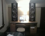
btw, below is a pic of the speakers with a very temporary layout. I find the scale hilarious. (They're used JBLs that cost me less than some of my engineering textbooks, I guess that really says two things... )
AM would make more sense, as accidentally capturing AM interference is easy. However, it exactly matches the broadcast on 105.3 FM, and they have no AM station. Holy smokes. I know how to correct the problem with additional filtering as described above (thanks again Gootee), but I am curious what component would have the ability to demodulate this. Any explanation?
btw, below is a pic of the speakers with a very temporary layout. I find the scale hilarious. (They're used JBLs that cost me less than some of my engineering textbooks, I guess that really says two things...
)Attachments
- Status
- This old topic is closed. If you want to reopen this topic, contact a moderator using the "Report Post" button.
- Home
- Amplifiers
- Chip Amps
- Basic chipamp component selection