They could have simply answered the question.
http://www.diyaudio.com/forums/pass-labs/182930-balanced-cascoded-f5-2.html#post2467359
http://www.diyaudio.com/forums/pass-labs/182930-balanced-cascoded-f5-2.html#post2467528
both N and P have 1A bias
but signal is either at N or P channel, shifting
not at both the same time
hmm, maybe not that so simple, or ?
I thought we were talking about quiescent conditions, not with signal running through circuit.
No.So you have 1 pair on each side (ie 2 pairs) which are in parallel. So simply add the currents of the parallel pairs.
So if you have 1A through each pair the total bias is 2A.
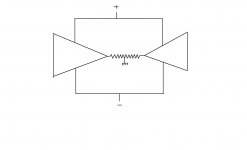
the two halves of the balanced amplifier are in series driving the common load.
That's why we get double the power into double the load impedance.
The two halves are not in parallel as far as operating like an amplifier are concerned. So you should not assume the analogy of paralleling the supply rail currents models the bias situation correctly.
Each half of the balanced (or bridged) amplifier is biased to 1.3A, i.e. 1.3A passes through the top emitter resistor down through the upper output device, carries on down through the lower output device and finally through the bottom emitter resistor.
This bias current determines the the maximum ClassA output current (2.6Apk) of the stage. The instructions tell you to bias the upper and lower devices together to maintain near zero output offset from this one half of the amplifier.
Then proceed to bias the other half, again to 1.3A. This too allows a maximum ClassA output current of 2.6Apk.
The load is in series with both halves of the amplifier and thus it is limited to 2.6Apk of ClassA current.
The sum of the two bias currents is 2.6A, the bias current is 1.3A.
Parallel and series are quite different.Take care not to confuse the two.
Last edited:
Another consequence of bridging /balancing.
Take two stock F5 biased at 1.3 each and arrange them into a balanced configuration. Each F5 will see half of the load wired to the balanced amp and so, leave classA at 12.5w only.
This balanced amp will also leave classA at 12.5w (P=IxIxload/2)
So, you already doubled the demand to the PSU but you have still to increase the bias if you want as much classA power as with the stock F5. (I leave you calculate how much)
Class A efficiency is way reduced and a lot of heat is to dissipate.
That's why it is sometimes better to start with lower rails. Except if what you want is higher class AB power only.
Last edited:
This gets pretty sticky dosen't it  for the most part AndrewT's discription is good but, I'm not sure everyone's going to take away the same ideas from what he said? Everything is correct of coarse but, these words don't always lend themselves to and accurate discription as everyone does not always see the same meaning.
For instance when he said "The two halves are not in parallel as far as operating like an amplifier are concerned." He was refering to signal current available at the output. This however is not true refering to power supply draw and Idle current where the 2 halves are in parallel.
When he said "So you should not assume the analogy of paralleling the supply rail currents models the bias situation correctly." The problem here is that AndrewT is refering to the bias, as current controlable by the input signal. Others however, my take that to mean the idle current through both the positive and negative legs of the amp in total and many forget to clarify this situation. Both legs of the amp are biased. The total is drawn by the power supply. The signal however, acts on both simultaniously in a series manor with the load (speaker) in the middle. There is no parallel connection of these bias currents to the load, only a series one.
Well, that's my 2 cents.
for the most part AndrewT's discription is good but, I'm not sure everyone's going to take away the same ideas from what he said? Everything is correct of coarse but, these words don't always lend themselves to and accurate discription as everyone does not always see the same meaning.For instance when he said "The two halves are not in parallel as far as operating like an amplifier are concerned." He was refering to signal current available at the output. This however is not true refering to power supply draw and Idle current where the 2 halves are in parallel.
When he said "So you should not assume the analogy of paralleling the supply rail currents models the bias situation correctly." The problem here is that AndrewT is refering to the bias, as current controlable by the input signal. Others however, my take that to mean the idle current through both the positive and negative legs of the amp in total and many forget to clarify this situation. Both legs of the amp are biased. The total is drawn by the power supply. The signal however, acts on both simultaniously in a series manor with the load (speaker) in the middle. There is no parallel connection of these bias currents to the load, only a series one.
Well, that's my 2 cents.
I disagree, I am referring to bias current and quiescent operating condition when output offset is precisely zero.For instance when he said "The two halves are not in parallel as far as operating like an amplifier are concerned." He was referring to signal current available at the output.
I did not use the term "Idle current". I am specifically referring to bias current. Because this is where some Members are becoming confused. Bias Current has a special meaning it is not equal to idle current.This however is not true referring to power supply draw and Idle current where the 2 halves are in parallel.
No. Bias current is set up and measured or checked when there is no signal present and no output offset current present. You ensure zero output offset current by removing the speaker load.When he said "So you should not assume the analogy of paralleling the supply rail currents models the bias situation correctly." The problem here is ...............as current controllable by the input signal.
From all the other parts of FLG's clarification it appears to me that he understands why the problem occurs (misunderstanding bias current) and also knows how to calculate or measure the bias current.
The bias current must be measured at the output devices. It is not the same as the current that passes along the supply rails. This is where many are getting tripped up.
Quiescent current is what the amplifier draws when no signal is present. That quiescent current can be different in the two supply rails if the output offset current is not zero.
Last edited:
Forget about everything X.
Look at the supply and look at the output mosfets.
If you have 1 A going through one side and 1 A going through the other side the current drawn from the supply is 1 + 1 = 2. It can't get simpler than that
Nice, even I can understand when its put that simply! your ability to reduce complicated theory in a way a lay person, (albeit a diy lay person) like me can understand. Everything should be as simple as possible...but no simpler-I think Albert Einstein said that, but dont hold me to it.
NYCo, your posts are similarly appreciated. I am watching your other threads too, thanks for your efforts. I have learned a lot from your posts, likely because you are also trying to work your way through this knowledge and theory.
Russellc
Hi Thanh,
Please excuse my ignorance, here ..
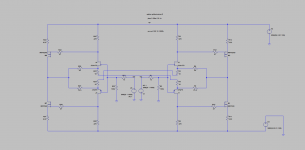
I just noticed the different values for the feedback resistors (55 & 73R) - could you direct me to where this came from? I completely missed this!
Also, does it also apply to the "normal" unbalanced cct or is specific to this balanced arrangement?
Please excuse my ignorance, here ..
I just noticed the different values for the feedback resistors (55 & 73R) - could you direct me to where this came from? I completely missed this!
Also, does it also apply to the "normal" unbalanced cct or is specific to this balanced arrangement?
Ah, what a shame - I thought something new had been found about the j74s!
I'm not sure if the Siemens or the Nichicons (SuperThru) caps are "my sound" for this amp - what have you tried? I think Jeremy is trying Rifa's, Bob Field also Rifa for 600Hz ribbons, and someone else using the Mundorfs - all have quite noticeably different sound.
I'm not sure if the Siemens or the Nichicons (SuperThru) caps are "my sound" for this amp - what have you tried? I think Jeremy is trying Rifa's, Bob Field also Rifa for 600Hz ribbons, and someone else using the Mundorfs - all have quite noticeably different sound.
Ah, what a shame - I thought something new had been found about the j74s!
I'm not sure if the Siemens or the Nichicons (SuperThru) caps are "my sound" for this amp - what have you tried? I think Jeremy is trying Rifa's, Bob Field also Rifa for 600Hz ribbons, and someone else using the Mundorfs - all have quite noticeably different sound.
It may have been ideas of Juma's I was playing around with.
I can't remember now.
- Status
- This old topic is closed. If you want to reopen this topic, contact a moderator using the "Report Post" button.
- Home
- Amplifiers
- Pass Labs
- Balanced F5 question