Those of you who still wish to follow my approach to audio, and to the F5X, and wish to understand why I am so uncompromising, you might be interested to read this post by John Curl :
http://www.diyaudio.com/forums/anal...rch-preamplifier-part-ii-132.html#post2363827
A lot of people find John difficult. Very few people would doubt his contribution to audio design.
And for me personally, that is the only thing that counts.
Patrick
http://www.diyaudio.com/forums/anal...rch-preamplifier-part-ii-132.html#post2363827
A lot of people find John difficult. Very few people would doubt his contribution to audio design.
And for me personally, that is the only thing that counts.
Patrick
Those of you who still wish to follow my approach to audio, and to the F5X, and wish to understand why I am so uncompromising, you might be interested to read this post by John Curl :
http://www.diyaudio.com/forums/anal...rch-preamplifier-part-ii-132.html#post2363827
A lot of people find John difficult. Very few people would doubt his contribution to audio design.
And for me personally, that is the only thing that counts.
Patrick
Please carry on, any word on the files from Variac? I would really like to build this amp! Hopefully the boards will be workable!
Russellc
AR2,
Please send me a email, so that I can arrange other things with you, like matched JFETs.
Thx,
Patrick
I've PM'd you, I am also interested in the matched fets, and anything else you recommend. I will be staying with the project.
Thanks,
Russellc
For those who wish to organise their own JFETs, the 2SK170's should ideally have an Idss of 6~7mA.
Going lower with Idss would increase the amount of negative feedback proportionally, and vice versa.
If you use the 5R degeneration on the 2SJ74, as I recommended, then you can calculate the Idss of the 2SJ74's using the following equation :
Idss (2SJ74) = Id * (1 + Rs.Yfs)
where Id = Idss of the 2SK170 in this case; Rs =5.1R; Yfs = 0.033 S for 2SJ74 at that bias range.
It works out to roughly 1mA higher than the Idss of the 2SK170s.
Get matched quads for both K170s and J74s if you can, so that both left and right channels are the identical.
Patrick
.
Last edited:
May I point out that in addition to the discussion in post #336 of the potential thermal performance of a copper pad at the MOSFET with increased area :
http://www.diyaudio.com/forums/pass-labs/172770-balanced-f5-question-7.html#post2347107
(in the previous case 40x50mm), this increased area also implies an increased capacitance between the MOSFET drain and the heat sink, the latter usually grounded.
Using the Kerafol 86/82 as insulator, which has a thickness of 0.25mm and a dielectric constant of 2.4, the capacitances are as follows :
Standard Toshiba 2SK1530 = 44pF
A copper pad of 40x50 mm = 170pF
A copper pad of 40x36 mm = 122pF
Considering only one half of the X, or the standard SE F5, the drain of both output MOSFETs are connected electrically to the amplifier output. This means that using such a heat spreader will increased the capacitive coupling of each output to ground from 88pF to somewhere between 250~340pF.
I have not done any Spice simulation as to what this extra capacitance would do to the stability margin of the circuit. But this should be taken into account in such considerations.
Patrick
Patrick
Tanks for the rough calculation of the capacitance.
It is certainly to be taken in to account and calculated exactly.
It may even improve the stability of the circuit and limit the bandwidth.
Quote from Balanced F5 question>I will do this one particular one, just to end the discussion.
No you will not end the discussion.
Still refreshing to see you dropped the WE form.
I will get handsaw and files out and do a simulation.
One thing came to mind the drain is at supply rail voltage so maybe the 100000 uF of the smoothing capacitors may even get a 340 pf increase so it will be
100000000340pF-smoothing capacitor wow same capacitance for free.
(Sorry if I missed a zero here and there).
But maybe I am wrong the bias resistor is between the drain and the supply and this take the 100000uF out of the equation.
Sorry go to go and get the meter out to measure capacitance between drain and ground.
Al over and out
> One thing came to mind the drain is at supply rail voltage ...
> But maybe I am wrong the bias resistor is between the drain and the supply
Suggest you check the Nelson Pass article and schematics to see whether it is the MOSFET source or the drain that is at (or near to) supply rail.
Nelson explained that very well. I cannot possibly do better.
http://www.firstwatt.com/pdf/prod_f5_man.pdf
Fig.5 to be precise.
Nice weekend to all,
Patrick
.
Last edited:
F5X PCB layout options
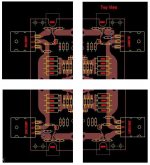
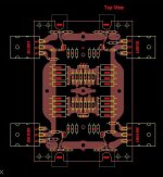
Given the heatsink and enclosure issues, has anyone considered breaking the PC board into smaller pieces could be placed at the optimal heatsink locations, in a larger variety of enclosures? For example, consider fracturing EUVL's layout from post #109 as follows.
EULV's original layout: F5X-layout.jpg
Fractured layout: F5X-fract.jpg
The issue is whether wiring issues between the pieces can be resolved to make this work well.
Attachments
Ok, could you guys get me up to speed? Is there a Gerber file ready with general agreement on it? Shouldn't we do a small run at first? Or is there a lot of demand for it Right Now? Is there a Group Buy thread for those who are interested so we have an idea of the numbers involved?
Instead of a Group buy thread or Wiki list the best way to do this might be for the store to have it listed as out of stock and backordered. That way people would be able to go to the store, order and pay now so that we know how many are interested enough to buy it, and have it automatically shipped out when the boards are done and arrive at our shippers.
Mark
Last edited:
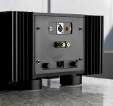
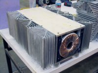
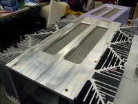
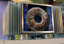
Since the conversation is about heatsinks and proposed case design, I just wanted to share with you cases I made about five years ago to give you idea of size and price that goes with that. As far as I remember, I paid something in the range of $ 600 - 800 just for heatsinks. It took me around 6 months of almost daily labor to produce these cases. All that I could say is, if Patrick stay in the rough price range for the cases he is trying to make for the diy comunnity, that would be the bargan. Just a labor alone to put together case, and machinery needed to do it properly will worth the price. Aluminum used in my cases, was expensive, very expensive, but I do not remember the number. Than add, finishing, nice screws... It really takes a lot to do it.
Attachments

Quote>But maybe I am wrong the bias resistor...

Course I am wrong the drain only see the capacitance of the load got to get the file out again and shave a bit of that of the Capacitors on the cross over on the speakers.
Or just swap the position of the shim whit the Kerafol as in plan A.
(I could not resist to spice things up a bit)
Did you really listen to the Jester and measure the capacitance of the copper spreaders?
Quote> Go and read....
Got 2 replays for that.
Funny one:
I repent of my sin and shall read Papa articles 15 times the Latin translation of course.
Not so Funny
Not the first time that we see articles by of someone else used here in this way
And a quote from Papa as well:
Go to Radio Shack and spend $30 on one of their cute little
infra-red temperature measurement thingies. It's great for
looking at transistors and heat sinks - set it for Centigrade.
When it shows your transistor case at 100 deg C, it's too hot.
In my opinion is very useful to get links to the Juicy bits here and there.
Al
Ps Have I forgot to put any spelling mistakes on this one?
Course I am wrong the drain only see the capacitance of the load got to get the file out again and shave a bit of that of the Capacitors on the cross over on the speakers.
Or just swap the position of the shim whit the Kerafol as in plan A.
(I
could not resist to spice things up a bit)Did you really listen to the Jester and measure the capacitance of the copper spreaders?
Quote> Go and read....
Got 2 replays for that.
Funny one:
I repent of my sin and shall read Papa articles 15 times the Latin translation of course.
Not so Funny
Not the first time that we see articles by of someone else used here in this way
And a quote from Papa as well:
Go to Radio Shack and spend $30 on one of their cute little
infra-red temperature measurement thingies. It's great for
looking at transistors and heat sinks - set it for Centigrade.
When it shows your transistor case at 100 deg C, it's too hot.
In my opinion is very useful to get links to the Juicy bits here and there.
Al
Ps Have I forgot to put any spelling mistakes on this one?
- Status
- This old topic is closed. If you want to reopen this topic, contact a moderator using the "Report Post" button.
- Home
- Amplifiers
- Pass Labs
- Balanced F5 question