And a "razor-sharp" edge would minimize that dipole moment ?
Could it be zero then ?
In theory it could be zero but the math would then blows up with singularities at the edges. This can be seen in the exact calculations for diffraction from a circular disk that were done many decades ago. In prolate spheroidal coordinates one can make the disk as thin as you want, except zero. At zero thickness the wave functions have a singularity at the disks edge.
A little aside - prolate spheroidal coordinates are what spinning black holes have to be analyzed in. The disk at the edge is the "singularity" and it is hypothesized that if you passed through this disk that time would jump backwards or to another place in the universe - a worm hole.
The prolate disk problem solution is in JASA way back in the 60's and was done by Dr. Lauchle of Penn State, one of my advisors. That's how I know of it.
So you are saying that the dipole edge sources only pertain to the case of the dipole baffle?
David
Each edge for each source is a monopole, the two out-of-phase side creates a dipole at the edge. As above, if the thickness of the edge goes to zero then the solution blows up. Edge diffraction for a single source is always a monopole. John K shows this as well.
... Edge diffraction for a single source is always a monopole. John K shows this as well.
For a single monopole source, I measure the diffraction impulse behind the shadow boundary to be opposite in phase to that measured in front of the shadow boundary. This was shown in the Vanderkooy paper (excerpt attached).
Wouldn't this indicate that the diffraction "source" is not a monopole? or are you making the distinction that the impulse behind the shadow boundary is due to diffraction and the impulse in front of the shadow boundary is from reflection.
Attachments

Hi,
The short version is :
Box diffraction generally causes a mild peak (~2dB) with ripple and
a general baffle step of 6dB if the box is away from boundaries.
OB diffraction generally causes a bigger peak and more ripple
unless the baffle is narrow like a box, but then transforms to
a baffle loss (not step) high pass acoustic roll-off of 6dB/octave.
The reason I said that they are fundamentally different is
that baffle loss is using up excursion capability of the driver,
as driver excursion is the same as an infinite baffle / free air.
rgds, sreten.
I get it.The value of the reflection coefficient (called r in following picture) does not seem to be so clear, between 0.5 and 0.7 ? see http://www.torean.dk/artikel/Diffraction.pdf
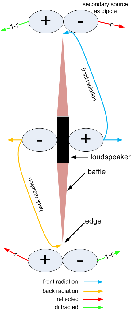
But in case of dipole loudspeaker, as the diffracted (1-r) and reflected (r) waves sum to unity in the front field, it is not so important to know the r value. I added it on the picture.
Thanks.
For a single monopole source, I measure the diffraction impulse behind the shadow boundary to be opposite in phase to that measured in front of the shadow boundary. This was shown in the Vanderkooy paper (excerpt attached).
Wouldn't this indicate that the diffraction "source" is not a monopole? or are you making the distinction that the impulse behind the shadow boundary is due to diffraction and the impulse in front of the shadow boundary is from reflection.
I didn't mention the phase of the shadow zone, but I do believe that it is the inverse of the field at the diffraction edge.
For a single monopole source, I measure the diffraction impulse behind the shadow boundary to be opposite in phase to that measured in front of the shadow boundary. This was shown in the Vanderkooy paper (excerpt attached).
Wouldn't this indicate that the diffraction "source" is not a monopole? or are you making the distinction that the impulse behind the shadow boundary is due to diffraction and the impulse in front of the shadow boundary is from reflection.
No. Try looking at this figure:
An externally hosted image should be here but it was not working when we last tested it.
The red wave is the source and the blue wave is the diffraction. From the front you see the impulse from red + wave, then the delayed pulse from the blue - wave. From the rear, or any angle past 90 degrees, the two wave are coherent with no delay so what you see is a single impulse resulting from the sum of the red and blue waves. It has the polarity of the red + wave but is lower in magnitude. This is because the magnitude of the red + wave is always greater than that of the blue - wave. So the rear pulse has the polarity of the red wave but reduced magnitude.
From the front , or any angle less that 90 degrees, the two pulse can be observed separately but for any angle of 90 or greater they are coincident and only the net sum is observed.
In reality there is also a loss of high frequency content in the rear wave due to directionality of the red source.
The thing here is there is a difference between looking at a model of diffraction and the effects, and looking at the result of diffraction. Edge diffraction is modeled by placing a monopole source with inverted polarity and reduced magnitude at the edge. What you measure is the result of diffraction as represented by this model.
edit: I just want to add that what is seen in the Vanderkooy figure from the rear is not the pulse of the diffraction source. It is the result of the wave being diffracted. From the front these can be isolated due to the differences in propagation time.
Last edited:
No. Try looking at this figure:
An externally hosted image should be here but it was not working when we last tested it.
From the front , or any angle less that 90 degrees, the two pulse can be observed separately but for any angle of 90 or greater they are coincident and only the net sum is observed.
In reality there is also a loss of high frequency content in the rear wave due to directionality of the red source.
The thing here is there is a difference between looking at a model of diffraction and the effects, and looking at the result of diffraction. Edge diffraction is modeled by placing a monopole source with inverted polarity and reduced magnitude at the edge. What you measure is the result of diffraction as represented by this model.
edit: I just want to add that what is seen in the Vanderkooy figure from the rear is not the pulse of the diffraction source. It is the result of the wave being diffracted. From the front these can be isolated due to the differences in propagation time.
I'm having a hard time reconciling this diagram, JLo's and the Lipshitz diagram.
jLo uses a reflection coefficient and wants r in one direction and 1-r in the other. Let's say the Vanderkooy figure shows a net reflection strength of 0.1, then the figure shows a front composite of 1-r where r is delayed and reduced to 0.1 and 1 is the tweeter response. On the back side the response is simply r = 0.1
You want us to think of the edge as a secondary source, a monopole giving a different effective polarity forwards and backwards by net combination of levels. For forward radiation the initial source and edge source are not time coincident so the are seen as a positive pulse and a negative 0.1 reflection. In the back side they are time coincident so we have level cancelation, but how do we get down to Vanderkooy's 0.1 level rather than 0.9?
When you mention the directionality of the red source, don't you mean of the blue edge source? The edge is illuminated by the 90 degree response of the driver, that is all it 'knows". From that point it is the directivity of the edge that determines diffraction.
I'm not seeing how we get a small negative reflection in the front hemisphere and an equally small positive diffraction (per Vandekooy) in back without thinking of the edge source as being a doublet. If the primary wave doesn't diffract, but just excites the edge radiation, then it can add up. Otherwise, how do we get to the positive and negative edge reflections as seen?
Finally, JLo is convincing himself that the net edge reflection cancels between front and rear contributions. I think that is missing a sign inversion needed somewhere so that r and 1- r don't cancel implying no edge reflections for a dipole. On the other hand it does seem that for the Bipole case we can have absolutely edge free performance as long as we have front back mirroring (and sharp edges) no matter what the perimeter shape.
David
Each edge for each source is a monopole, the two out-of-phase side creates a dipole at the edge. As above, if the thickness of the edge goes to zero then the solution blows up. Edge diffraction for a single source is always a monopole. John K shows this as well.
How do we reconcile this with the Vanderkooy measurement showing the inverted phase delayed reflection/diffractions?
David S
This is a very interesting discussion !
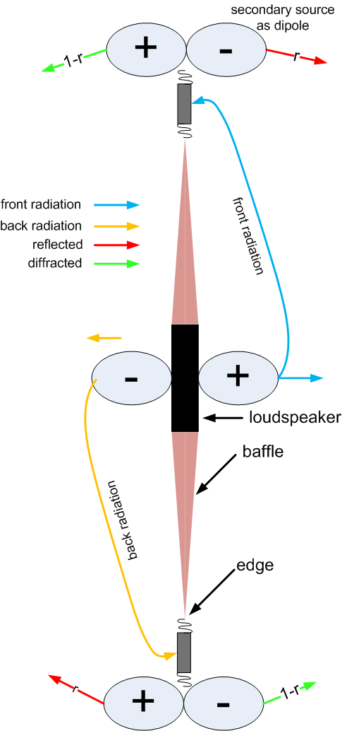
To better explain why diffraction can be modelled as dipoles on the edge, I modified the drawing.
Imagine that the air at the edge is replaced by a very light membrane, this membrane is moved by the incident signal and acts as a dipole :
radiating to the back in phase with incident signal and reflecting to the front in phase opposition.
In the model I tried to explain, baffle step and baffle loss are exactly the same phenomen due to one single cause, diffraction.
- when there is no backward radiation (loudspeaker in a box), the level decreases to -6dB at lowest frequencies (call it baffle step)
incident + reflected from front in phase opposition = 1-r = 0.5 (when r=0.5)
- when there is backward radiation (OB), there is total cancellation at lowest frequencies
incident + reflected from front in phase opposition + diffracted from back in phase opposition = 1-r-(1-r) = 1-0.5-(1-0.5) = 0
This model also explains why ripples are doubled in case of OB.
To better explain why diffraction can be modelled as dipoles on the edge, I modified the drawing.
Imagine that the air at the edge is replaced by a very light membrane, this membrane is moved by the incident signal and acts as a dipole :
radiating to the back in phase with incident signal and reflecting to the front in phase opposition.
Box diffraction generally causes a general baffle step of 6dB
OB diffraction transforms to a baffle loss (not step) high pass acoustic roll-off of 6dB/octave.
They are fundamentally different
In the model I tried to explain, baffle step and baffle loss are exactly the same phenomen due to one single cause, diffraction.
- when there is no backward radiation (loudspeaker in a box), the level decreases to -6dB at lowest frequencies (call it baffle step)
incident + reflected from front in phase opposition = 1-r = 0.5 (when r=0.5)
- when there is backward radiation (OB), there is total cancellation at lowest frequencies
incident + reflected from front in phase opposition + diffracted from back in phase opposition = 1-r-(1-r) = 1-0.5-(1-0.5) = 0
This model also explains why ripples are doubled in case of OB.
These two figures are showing the same thing but using different terms. The figure to the left is showing the result of diffraction. The figure to the right is showing how diffraction can be modeled with two monopole sources, one for the speaker and one for the effect of the sound wave interacting with the baffle edge. Noting is changing sign. the front impulse shows +1 then at a time later -r. The rear impulse shows one impulse of magnitude (1-r). The secondary source is always of magnitude r and - polarity. r is less than 1 so 1-r is positive the same as the first pulse from the front. The diffraction is not changing sign.
Again, there is a difference between modeling edge diffraction by placing a monopole source at an edge (right figure) and looking at the result of diffraction (left figure).
Again, there is a difference between modeling edge diffraction by placing a monopole source at an edge (right figure) and looking at the result of diffraction (left figure).
An externally hosted image should be here but it was not working when we last tested it.
Last edited:
Another thing. When modeling the diffraction the use of the two sources allows you to look at the effect of off axis angles. On axis from the front the path length from the diffraction source is 1/2 the baffle width greater than that of the direct source, giving rise to the time delay between direct and diffracted waves. However, as you move off axis this path length difference becomes less and less, until at 90 degrees the path lengths are the same. The difference go sort of like W/(2C) cos(Theta) where W is the baffle width, C is the sound speed, and Theta is the off axis angle. Past 90 degrees the path length difference remains 0 and there is no secondary impulse.
These two figures are showing the same thing but using different terms. The figure to the left is showing the result of diffraction. The figure to the right is showing how diffraction can be modeled with two monopole sources, one for the speaker and one for the effect of the sound wave interacting with the baffle edge. Noting is changing sign. the front impulse shows +1 then at a time later -r. The rear impulse shows one impulse of magnitude (1-r). The secondary source is always of magnitude r and - polarity. r is less than 1 so 1-r is positive the same as the first pulse from the front. The diffraction is not changing sign.
This makes sense with regard to polarity but not with regard to level.
Again, looking at the Vanderkooy diagram, you would say that we have a delayed forward reflection of about 0.1 (but polarity inverted). If the diffraction around the boundary is 1 -r then we expect to see 0.9 in the rearward direction. Rather we see 0.1 again.
It makes more sense to me, as I think about it, that the edge contribution is a dipole (even for the non dipole enclosed box case. Imagine a hemispherical wave front moving down a baffle away from a source. For particles along the boundary there are other adjacent particle in the same pressure front to one side, so they can't expand that way. On the other side there is a rigid boundary so you can't expand that way. A positive pressure peak moves down the baffle and can only travel out radially.
Now the wave front gets to the edge of the boundary and Bam! suddenly zero pressure to the left of me! I'm going to start expanding to the left. From the edge of that boundary the particles start expanding to the shaded side beyond the plane of the previous boundary. Surely that starts to increase pressure in that direction (behind the baffle plane). Surely particle velocity away from the previously constrained hemisphere creates a negative wave front in the forwards direction (ahead of the baffle plane). Positive velocity in one direction and negative velocity in the other, that sounds like a doublet to me, including no pressure change at some angle along the previous wave front direction.
Regards,
David
This makes sense with regard to polarity but not with regard to level.
Regards,
David
The thing you are missing is that the rear impulse looks different because the direct wave that travels along the baffle surface (90 degrees off axis) doesn't contain the same spectral content as the direct wave on axis. The axial impulse has a lot of high frequency content that is absent from the 90 degree wave. It's just a consequence of the directivity of the speaker. It is not a point source. Put a speaker in an infinite baffle and measure the response on axis and with the mic on the surface of the baffle. You will see very different impulses. Look at the Vanderkooy plots for the front response. Ignoring amplitude, The diffracted impulse doesn't look anything like the initial speaker impulse. The large initial spike is gone because all the high frequency content is gone. It's a much more complex process that just saying the acoustic wave from the source propagates uniformly in all directions. That is true at low frequency which is ultimately why the baffle step is 6dB. But if it also di so at high frequency you would see much larger diffraction artifacts in the high frequency response of a speaker than a couple of dB.
Other than that it's simple physics. When an acoustic wave turns abruptly into an expanding area a wave of the opposite family (polarity) emanates from the point where the expansion starts. The response at any point in space is then the sum (superposition) of the two waves.
It makes more sense to me, as I think about it, that the edge contribution is a dipole (even for the non dipole enclosed box case. Imagine a hemispherical wave front moving down a baffle away from a source. For particles along the boundary there are other adjacent particle in the same pressure front to one side, so they can't expand that way. On the other side there is a rigid boundary so you can't expand that way. A positive pressure peak moves down the baffle and can only travel out radially.
I am not shure, whether we can decide any of these descriptions being "right" or "wrong". But i can follow your visualization rather well.
When i imagine a line source mounted to an infinitely long (high) baffle, but the baffle having finite dimensions to the sides, there will be no velocity component rectangular to the baffle as the (infinitely high) cylinder shaped wavefront is spreading out on the baffle, because the baffle does not "allow" particle movement rectangular to the surface.
But with the wavefront reaching the edge there is "immediately" a new velocity component (resulting from a pressure gradient) pointing towards the shaded side of the baffle.
That velocity component should be orthogonal to the baffle plane. I can imagine it as a dipole component, which also occurs in case the baffle is excited by a monopole source (from the "front" side) only.
If the baffle is excited by a dipole source (positive at front, negative at the rear side) then that "edge dipole component" should be doubled (double particle velocity, resulting from double pressure gradient).
The "edge dipole component" would be zero for 90 degrees off axis or "in the baffle plane". But it would interfere with the "primary sound source" at all other angles ...
Of course that energy needed for the "edge dipole component" - the particle acceleration - must be "eaten up" from the primary wavefront, is that right ?
Last edited:
gedlee said:But we must always remember than whenever there is diffraction there must be a reflection so the two things are intimately connected in a way that makes them virtually inseparable. Which is why we often call the forward field from a baffle edge diffraction when in fact it is the forward reflection that results from the true diffraction into the shadow zone.
... i hope at least i understood this so far.
So a software capable of (just) modelling the forward field resulting from edge diffraction of a (boxed driver) monopole loudspeaker places virtual monopole sources along the baffle edge, which in fact simulate the reflection interlinked to the diffraction, which fills the space in the rear of the cabinet.
If that software - like "Edge" - has a dipole toggle, those virtual monopole sources have to simulate
- the (forward) reflection interlinked to the (rear) diffraction caused by the forward radiation of the driver
"plus"
- the (this time "true") diffraction coming around the edge caused by the rear radiation of the driver
Both - reflection and diffraction components - represent low pass filtered versions of the on axis spectrum due to the directivity of the driver and the baffle itself.
Last edited:
Would covering the baffle with acoustic felt, like e.g. Wilson Audio does on their closed box baffles, be a way to reduse baffle diffraction on an open baffle? (Especially in the higher frequences)
Or will this actually have an diminishing effect on a dipole? (Reduce the 0-effect in the 90-degree off axis)
Or will this actually have an diminishing effect on a dipole? (Reduce the 0-effect in the 90-degree off axis)
The thing you are missing is that the rear impulse looks different because the direct wave that travels along the baffle surface (90 degrees off axis) doesn't contain the same spectral content as the direct wave on axis. The axial impulse has a lot of high frequency content that is absent from the 90 degree wave. It's just a consequence of the directivity of the speaker. It is not a point source. Put a speaker in an infinite baffle and measure the response on axis and with the mic on the surface of the baffle. You will see very different impulses. Look at the Vanderkooy plots for the front response. Ignoring amplitude, The diffracted impulse doesn't look anything like the initial speaker impulse. The large initial spike is gone because all the high frequency content is gone. It's a much more complex process that just saying the acoustic wave from the source propagates uniformly in all directions. That is true at low frequency which is ultimately why the baffle step is 6dB. But if it also di so at high frequency you would see much larger diffraction artifacts in the high frequency response of a speaker than a couple of dB.
I understand that the axial response of the tweeter has greater HF energy and therefore a taller impulse. As I mentioned before, the edges only know the 90 degree response of the transducer. Still, if the combination of reflection coefficient and 90 degree response adds up to 10% amplitude for the edge reflection, you still need to answer how we get 10% at the front (inverted) and 10% to the rear (equal strength), when the rear is defined by 1-r (giving 90% in my mind).
Why are the front and rear reflections (diffractions) equal amplitude?
David
speaker dave said:As I mentioned before, the edges only know the 90 degree response of the transducer.
Which is the 90 degree radiation as observed at the baffle edge caused by a concrete baffle applied to a concrete driver ...
Figure 3.1:
Here directivity indices of ideal pistonic drivers are shown under different idealized mounting conditions.
- parameter is Krm
- directivity index is at the left axis
- upper curve is "pistonic radiator without baffle"
- middle curve is "pistonic radiator in infinite baffle"
- lower curve is "pistonic radiator mounted at end of infinetely long tube"
from
Heinz Sahm, "HiFi-Lautsprecher", Franzis 1978
It seems interesting, that the baffled driver has even lower DI
than the "tubed" one without baffle e.g. for Krm = 2.
Attachments

Last edited:
- Status
- Not open for further replies.
- Home
- Loudspeakers
- Multi-Way
- Baffle edge diffraction with dipole radiation