I'd incline to stick with that B200 for now. 18L is alright if you stuff a sock in the reflex. I was really trying to figure out a crossover for you. I'd think you won't have much difficulty matching it to a 89dB or better tweeter with a third order crossover, like a Seas Prestige 27TFFC or Morel Classic CAT298. But you could even just buy a cheapie dome and run it off a single 2.2uF.
...
Enjoy the pictures of your B200 in it's youth!")
Haha, great stuff
Ok, i've found an italian seller who sells the tweeter you suggested (and many others...). Actually I've this dome:
- Audiokit E-commerce - Vendita componenti elettronici
pretty flat response, not bad I think but I can't find a review....
Anyway, I'm going to build a new cabinet: the one I have now is a bit "damaged"... Too many times I've opened and closed it due to vary experiments
.... 30/35 liters, port tuning at 45Hz even this time...Anyway I prefer reflex design: one speaker is in a corner, the second along a wall .... So I can "match" the frequency response simply closing the reflex of the speaker in the corner...
RDLewis, I can't understand why KEF used this strange crossover design...
Many years ago I aquired A B200 from a friend, who used it as the bass unit in a three way TL. I decided to try it in one of the 2 way designs common then using the above (largely Kef type), but using an Audax tweeter, I could not stand the T27. Anyway, the results were pretty poor, undynamic, flat, coloured. I could not understand why it was held in high regard.
A few days latter I decided to try it out with a simpler Crossover, namily a single inductor, I think it was 1mH, and second order tweeter section. The difference was amazing. It showed me that the B200 was a much better driver than I thought. I have heard similar improvements from those who did similar things with the B110. The old KEF crossovers just sapped the life out of those drivers, all with aim to get the flattest response.
I think you could be onto something there RD, bextrene is heavily damped and quite forgiving of programme material. I think a little liveliness at the expense of colouration is worth trying!
Michelino, don't dump that tweeter of yours on a whim. Is there any reason to think it's bad? But FWIW, Vifa XT19 and XT25 are pretty good too. The crossover design is definitely wrong. I'm thinking 1.2-1.5mH and 7uF now for the B200. Maybe a 2-3 ohms resistance on the shunt too.
An externally hosted image should be here but it was not working when we last tested it.
Hi,
Come on people .... how can you take a x/o circuit that gives
a near short across an amplifier at high frequencies seriously ?
Its wrong, very wrong, people do make mistakes ....
If you swapped the position of the inductor and the notch
filter it would make a lot more sense*. As it stands you
have a 12uF path to ground (7uF + 5uF) which is 3 ohms
at 4.5KHz, 1.5 at 9KHz and a crushing 0.75 at 18KHz.
I guess circuit simulators still don't do smoke very well.
TinaTi has a nice option : an impedance meter, try that.
rgds, sreten.
*That would then be standard topology for a notch
filter below the x/o point, and pretty standard for
bextrene units, having a big midrange peak.
(Bextrene = rubberised polystyrene + a plastiflex
damping layer, which only controls the peak but
doesn't eliminate it, hence driver variability.)
The high value of the inductor may be due to it
doing BSC duty and reducing a midrange peak
in combination with the notch filter, hard to
say in a sim without the drivers response.
Last edited:
You can see the trap is before the capacitor here, the 5uF being top right:
So is the 3.29mH by the look of it.
An externally hosted image should be here but it was not working when we last tested it.
So is the 3.29mH by the look of it.
Hi,
I don't care, perhaps the board is wrong. 12uF across the input is wrong.
i've seen completely wrong x/o boards before, somebody gets it wrong.
12uF to ground is 12uF to ground, very low high frequency impedance.
Its not intentional I'm sure. I'm sure the positions should be swapped.
It should look like those x/o's in post #33.
Here it won't stop the speakers working, but its wrong, very wrong.
rgds, sreten.
Last edited:
You can see the trap is before the
capacitor here, the 5uF being top right:
So is the 3.29mH by the look of it.
Hi,
That is a viable arrangement, both before the capacitor.
rgds, sreten.
I think the simple answer is that the x-over in #34 has an error. If you look at the lines near the bass inductor indicating wires there seems to be a cut and paste job that suggests a later alteration. Having the large inductor feeding the small cap across the bass unit would make complete sense and the values would not be outrageous. Both the B110 and B200 had peaks around 3k. Depending on the baffle size these could be 8-10 db. A over damped second order configuration was not uncommon. (I have schematics for at least 7-8 combinations of KEF bass units and various tweeters.) E.g. the Wilkinson 2-way stepped baffle design (B200//T15, Wireless-World from about 1978) had the bass signal passing through a 2mH coil to a 2uF cap for a 3kHz x-over. Totally non-standard values but measured fine apparently.
Cheers, Jonathan
Cheers, Jonathan
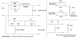
I think I'm becoming obsessed with this KEF Calinda crossover. It interests me, because 8" bass plus 1" tweeter is such a common design and I'm figuring what to do with mine.
To recap, here are the main T-S parameters for a KEF B200 SP1054 8" bextrene bass/mid (large magnet, low Q. n.b. Other B200 models had Qts around 0.45 and Le around 0.25mH):
Vas 130L
Qm 3.27
Qe 0.25
Qts 0.23
Le 0.45mH
Re 7.0R
Fs 25Hz
Main parameters for T27 SP1032:
Le 0.05mH
Fs 900-1100Hz
Re 5.2-5.6R
I've redrawn the schematic to reflect what we think it really was. And I've added some appropriate calculated Bafflestep and Zobel values for those who know about these things. So we've now got a bit of a cookbook if you allow for how they interact.
Attachments
Hi,
My bad regarding the 12uF, of course it would be 3uF which
isn't half as bad, a quarter in fact, but it would still be strange.
With 5uF across the driver a zobel is not a good idea, probably,
as any driver inductance will "help" the x/o, not hinder it.
Back of an envelope indicates the trap filter is centred on 1.9KHz,
sounds about right, you really need to know the drivers response.
The big inductor is doing the baffle step stuff.
rgds, sreten.
Last edited:
It would be going off-topic to discuss series crossovers. But there's a lot to like about them. Very nice impedance for one thing, but I don't think they are particularly efficient or cheap! You are adding a LCR at the input in effect.The whole point of my posting was to design a new crossover using a series configuration. A lot less current wasted to drive the speakers.
SEAS CNOcost no object
I definitely have a series crossover on the backburner though.
I don't understand why you made that statement. Series crossovers are passive not active circuits.
Bi-wiring and bi-amping are not the same thing.
Planet10 I would love to know where the deigner of the consoles came up with the idea of using a series circuit. I would think that it came about by just trying it. I doubt the answer will never be found.
The various AES papers are the earliest written text on their design that I am aware of.
Were the consoles used for recording or mixing a live performance. I know Olson designed tube amps. Any info would be quite educational and nostalgic.
The various AES papers are the earliest written text on their design that I am aware of.
Were the consoles used for recording or mixing a live performance. I know Olson designed tube amps. Any info would be quite educational and nostalgic.
- Status
- This old topic is closed. If you want to reopen this topic, contact a moderator using the "Report Post" button.
- Home
- Loudspeakers
- Multi-Way
- B200 Kef Drivers