the input impedance of a jFET Follower is very approximately 1Tohm||a few pF
How long are the cables from the phono to the RIAA pre?
At least 10" long to get along the arm and down to the pillar. If you can get them shorter than 18", then that's about as low as you can get, short of the RIAA pre being inside the headshell.
Place your phono pre as a TT plinth with the input sockets directly below with a coiled pair of wires up to the pillar. These curly wires must be dressed to maintain your TT suspension.
Last edited:
I tried it and it worked without issue. Ideally input impedance should be large and output impedance minimum.
Sent from my E6 using Tapatalk
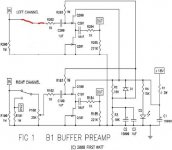
Ok. So, your B1 is now as on this schematic (I modified only one channel):
Attachments
But there's the pot on the original B1 (or 1M resistor on Omishra's circuit) that lower this enormous impedance, isn't it.the input impedance of a jFET Follower is very approximately 1Tohm||a few pF
1M should be OK given that the output impedance of the phono pre is 3K.
(I apologize if my questions, since the begining of the conversation, are stupid but my electronic skill is near zero.)
My phono cable is approximately 50cm (20") from pillar to phono pre. I don't think I can get it shorter to go from wallshelf to hifi rack.How long are the cables from the phono to the RIAA pre?
At least 10" long to get along the arm and down to the pillar. If you can get them shorter than 18", then that's about as low as you can get, short of the RIAA pre being inside the headshell.
Place your phono pre as a TT plinth with the input sockets directly below with a coiled pair of wires up to the pillar. These curly wires must be dressed to maintain your TT suspension.
(the TT is not suspended, so no need of fancy cable dressing as with my ex-LP12
") )
)PS: I really like your signature.
Last edited:
Yes that was source side buffer whose output fed to volume pot.Ok. So, your B1 is now as on this schematic (I modified only one channel):
Sent from my E6 using Tapatalk
the Buffer is NOT a volume control.
The Buffer is added to enable an inadequate Source to drive the next cable.
Phono cart >> cable >> Pre-amp >> RIAA >> Pre-amp >> cable >> control switching >> vol pot >> cable >> power amp.
Notice there is a minimum of three cables in that arrangement.
Each Source must be cable of driving the subsequent cable.
Your 300ohms source should be good, your 3000ohms sources is potentially a problem , the pre-amp after the RIAA. It appears to have an amplifier as the final output and typical of amplifiers it has a high output impedance. All this needs is to add a follower (Buffer) to the output. Did you look at the Salas RIAA?
Last edited:
That's exactly what I want to do.the Buffer is NOT a volume control.
The Buffer is added to enable an inadequate Source to drive the next cable.
All this needs is to add a follower (Buffer) to the output. Did you look at the Salas RIAA?
You must be talking about the Simplisic NJFet RIAA. It must be a good project, but the thread is so long that I didn't take time to study it.
I thought it should be more simple (and cheaper) for me to just add a buffer board in my existing phono pre, rather than starting from zero with a brand new project (new psu, new pre...).
If I take a "no volume control B1", I just have to put it in the case, solder it to the output of the RIAA board then to output's RCA and power it with the 24V psu. It can't be more simple.
If it's possible according to you.
I have to check if I can lower the voltage of the PSU. It's not home made but a commercial product (Custom Hifi Cable DC2) I bought second hand, before entering the DIY world.
I presume there must be a trimmer somewhere to adjust output voltage.
PS: B1 is a 2 transistor Jfet follower, isn't it?
I presume there must be a trimmer somewhere to adjust output voltage.
PS: B1 is a 2 transistor Jfet follower, isn't it?
I opened the PSU, found the trimmer and was able to lower the voltage down to 20V (lower is possible, I was not at the end of the trimmer's range). So powering a Jfet follower is possible (the Boozhound can work wtih 18 to 24V).
I think I just have to order a B1 PCB+Jfet kit from Passdiy.
I think I just have to order a B1 PCB+Jfet kit from Passdiy.
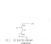
Like on the B1 schematic, except for the values, if I understand correctly.OUT feeds a 100r and that feeds a 1uF cap that feeds the RCA socket.
There's a 1µF capacitor at the output of the preamp (schematic here). Do I need to add one at the input of the buffer.The existing output needs you to identify the output at the last transistor.
You attach a capacitor between that output and IN.
No need to have resistors between IN and ground and between OUT and ground?
Last edited:
insert the 2Q after the 1uF.
Move R13 to the output. It is there as a leakage grounding path.
AC couple the output with a further 1uF.
This will suit all Zin down to 100kohms.
Why the booze did not include a line driving buffer is beyond explanation.
BTW, the Zout you measured is related directly to the value of R11.
You did not need to measure it. It is there for you to read.
insert the 2Q after the 1uF.
Move R13 to the output. It is there as a leakage grounding path.
AC couple the output with a further 1uF.
This will suit all Zin down to 100kohms.
Why the booze did not include a line driving buffer is beyond explanation.
BTW, the Zout you measured is related directly to the value of R11.
You did not need to measure it. It is there for you to read.
The original Pacific pre didn't have any buffer neither. The Boozhound worked very well with my previous amp (tube integrated amplifier with 100k input impendance). This very simple design fits certainly better this kind of load. By the way, Boozhound sells a buffer stage and it seems that the new new phono stage has a buffered output.
I tried to make a sketch following your advices (see attached file). Is it OK like this or did I misunderstood something once again?
I looked at Salas preamp and saw that there's no coupling cap between the amplifier Q and the buffer. Is it poosible for me to get rid of it or is it specific to Salas's design?
Concerning R11 and the impedance, somebody explained me that too... after I made my measures.
I can't remember if Salas RIAA is a dual polarity circuit, or single supply.
That makes a difference on whether a different DC voltage exists where the connection needs to be made.
It would be easy to include the AC coupling capacitor and after the build measure the DC voltage across it.
If zero mVdc, then the cap can be shorted out.
A 1uF MKT costs a few pence.
A 1uF MKP, or FKP, will cost more and require more space.
The new Booze (Deluxe JFET Phono Preamp) looks much better.
BTW, 10uF allows down to 10k Zin.
Just copy that. Except I suggest you add a 100r at the output from the jFET. To minimise the effect of parasitic capacitances of traces and wires etc.
I can't see your suggested modification.
Last edited:
- Home
- Amplifiers
- Pass Labs
- B1 preamp build thread