From the manual: "A regulated supply is better, but the circuit is pretty good at ignoring noise on the supply and minor fluctuations."
The large caps are for filtering PSU noise and to be able to cope with an unregulated PSU. At least, that's my interpretation of what Nelson wrote. I don't think Nelson envisioned what you're proposing. That's why Nelson wrote that "the value of C1 and C2 is not critical, and you can use as low as 1000µF". With C1=1000µF and R1=1ohm you get a first order low-pass filter @ 159Hz. Not a filter value that's very good at filtering mains hum.
You are of course free to hook up the outputs of the MUR860 diode bridge to the B1. Please report back your experiences. We, myself included, might even learn something useful!
Note that Nelson sold his commercial B1 with a SMPS to provide the B1 with some juice.
Your gainclone might have a higher PSRR...
I am looking to power up my B1 now as it's all soldered up.
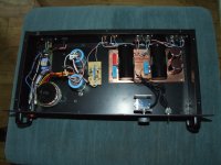
The board not a Pass Labs, but a clone. It has a shared section consisting of 2x 15,000uF caps, a diode, led and resistors before the gain stages, as in the Pass schematic. Isn't this stuff the tail end of a power supply?
Could I simply use a small toroidal transformer and a MUR860 diode rectifier I have spare to supply 18v DC to the unit? Would that be sensible?
There is/was a B1 clone at ebay. I wonder, is that NP approved, or..?
There is/was a B1 clone at ebay. I wonder, is that NP approved, or..?
Yeah, I feel a bit bad about that. I asked for a recommendation for a buffer design/kit here on diyAudio, and was advised to buy a "B1 board off ebay for peanuts". I looked it up and it looked real quality for $10, so I bought it right away. I wasn't even aware at the time that I could have bought from Nelson Pass for almost the exact same cost. Had I known I certainly would have bought from Passlabs.
Lucas
Would it be worth trying a high capacitance unregulated supply? I was thinking about 45000uF after the rectifier, then 1 ohm followed by 30000uF for C1?
As you might have guessed, I have plenty spare 15000uF caps to play with")
What would be the strengths and weaknesses compared to a standard LM317 regulated supply?
As you might have guessed, I have plenty spare 15000uF caps to play with
What would be the strengths and weaknesses compared to a standard LM317 regulated supply?
Pass suggests an unregulated supply for the B1. He specifies 30mF for the final/only stage of smoothing.Would it be worth trying a high capacitance unregulated supply? I was thinking about 45000uF after the rectifier, then 1 ohm followed by 30000uF for C1?
As you might have guessed, I have plenty spare 15000uF caps to play with
What would be the strengths and weaknesses compared to a standard LM317 regulated supply?
I would be tempted to try 10uF X1 or X2 across the transformer primary, then 30mF after the rectifier, and finally two 1r0 resistors, each feeding 30mF to individual channels of B1. Gosh, 90mF for a buffer!!
Last edited:
Thanks both for the feedback. I'm building a new B1 at the moment and will follow Andrew's advice.
I have a transformer with 15Vac secondary, so I should get 21.21V with normal mains voltage. This sits nicely in then middle of the 18-24V range, so fluctuations in mains voltage shouldn't be too much of an issue.
I remember reading an argument against using a regulated supply with zero feedback gain stage... can't remember the exact reasons.
Hi folks.
Hoping someone here can help with selecting an appropriate transformer for the B1. My head's in a spin with the varieties of PSU options available i.e. transformers with 0-18V secondaries, or 18-0-18V CT versions. Full wave/half wave/bridge rectifiers etc.
Basically I have a Peter Daniel PSU board which I'm re-using from a past project. I also have an LM317T which I'll use with a 240R/5K adjustable resistor to get the required output, which I've decided will be 24V (the max. voltage Mr Pass mentions in the build PDF).
Is it best to use a CT 18-0-18v transformer with just two MUR860 (I have four of these) diodes, or a 0-18V transformer and four MUR860s? A bit of help to aid this layman would be most greatfully accepted
Thank you,
- John
I'm using 9-0-9 30Va toroid + WOO1 bridge + 4700uF + 2R2 + 4700uF
Someone suggested running B1 at 22V so I'v got a straightforward LM317 reducing the 25V from the CRC down to 22V. But to be perfectly honest it runs silently and perfectly at 25V from my basic PSU.
Nelson's original B1 only used a Wall-Brick and the on-board 15000uF 1R0 15000uF gets rid of any noise.
I wouldn't recommend an SMPS wall brick.
Attachments
I'm using 9-0-9 30Va toroid + WOO1 bridge + 4700uF + 2R2 + 4700uF
Someone suggested running B1 at 22V so I'v got a straightforward LM317 reducing the 25V from the CRC down to 22V. But to be perfectly honest it runs silently and perfectly at 25V from my basic PSU.
Nelson's original B1 only used a Wall-Brick and the on-board 15000uF 1R0 15000uF gets rid of any noise.
I wouldn't recommend an SMPS wall brick.
Yes I'm using 9-0-9 as a single 18V supply which is then rectified which gives about 25V after the caps.
Just reviving an old thread - I did a standard B1 a year or so ago - used two 15000uf panasonic and recommended resistor on the pcb - psu was an old SMPS from an IBM laptop. The preamp sounded very well i thought, so did anyone else who borrowed it. Last weekend i did a simple regulated psu with a LM317, and what a difference! The detail level of my system has gone up a couple of nothces - most noticable i can now hear reverb/decay of notes where there used to be nothing... Something I should have done long ago!
Best regards
Hans
Best regards
Hans
Hi all, better late than never I have discovered the B1, and am gearing up to build one
I am a bit confused on the power supply (PS) though, even as I realize almost anything will work. After many hours of research, I am not much wiser, so must pose the question here. Please forgive me, if it seems trivial..
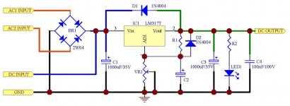
As I understand it, a simple regulated 18v+ PS will do fine, where only the positive voltage is filtered.
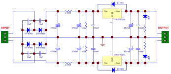
But would it be better (theoretically at least) to use a symmetrical PS that gives regulated and filtered +/-18v?
I have attached schematics of both types of regulated boards. Which is best suited for the B1? (assuming matching transformer).
Your help would be much appreciated!
I am a bit confused on the power supply (PS) though, even as I realize almost anything will work. After many hours of research, I am not much wiser, so must pose the question here. Please forgive me, if it seems trivial..
As I understand it, a simple regulated 18v+ PS will do fine, where only the positive voltage is filtered.
But would it be better (theoretically at least) to use a symmetrical PS that gives regulated and filtered +/-18v?
I have attached schematics of both types of regulated boards. Which is best suited for the B1? (assuming matching transformer).
Your help would be much appreciated!
Attachments
As designed, the B1 needs a single ended supply. A bipolar supply will not work. If you search for the DCB1, I believe you will find a variation that can use a bipolar supply.
But would it be better (theoretically at least) to use a symmetrical PS that gives regulated and filtered +/-18v?
My advice, stick with the B1 as Nelson designed it. It is a GREAT preamp!
As designed, the B1 needs a single ended supply. A bipolar supply will not work. If you search for the DCB1, I believe you will find a variation that can use a bipolar supply.
My advice, stick with the B1 as Nelson designed it. It is a GREAT preamp!
The mods to make it work from a bipolar supply are pretty trivial. doubly so if you perfboard the design. Depends how much you hate coupling capacitors. I had an RS encapsulated power supply lying around that had been £5 on ebay and gave +/-15V rails and that works with no fuss. Just match the FETs as closely as you can and you should get DC offsets in the 1-2mV range.
I currently don't have strong feelings regarding coupling caps, one way or the other (maybe I will as I learn more about this stuff..)
If a symmetrical power supply is built with LM317 and multiturn pots, wouldn't it be possible to adjust the DC offset almost to zero? -Or which FETs are you referring to?..
(maybe I will as I learn more about this stuff..)(...) Just match the FETs as closely as you can and you should get DC offsets in the 1-2mV range.
If a symmetrical power supply is built with LM317 and multiturn pots, wouldn't it be possible to adjust the DC offset almost to zero? -Or which FETs are you referring to?..
You can do it that way, and I believe the DCB1 PSU design allows that. I matched IDSS on mine to within 0.1mA or better which gave me DC offset in the levels I needed. I got an 8pack from the store and manged 3 matched sets from that. The last pair gave me 35mV offset so I either need coupling caps with those or another form of adjustment. In theory the closer the matching the better the performance, but that is as much to set expectation bias as audible improvment.
There is choice. Choice is gooood.
Only had mine in the system for a week now, but so far its doing exactly what it says on the tin.
There is choice. Choice is gooood.
Only had mine in the system for a week now, but so far its doing exactly what it says on the tin.
If you are going to the trouble to use LM317/337's then why not use a basic zener emitter follower regulator. Its about the same amount of parts and will perform better than the 3-pin reg's. You could use stacked matched LED's or a single zener for the voltage reference. Its more difficult to get the matched rails this way due to the fact there is no potentiometer, but for the average DIYer its not that hard.
If you decide to use the LM317/337's then you could use the same LED's or zener for the reference as the noise performance is supposed to be much better than with a potentiometer.
If you decide to use the LM317/337's then you could use the same LED's or zener for the reference as the noise performance is supposed to be much better than with a potentiometer.
- Status
- This old topic is closed. If you want to reopen this topic, contact a moderator using the "Report Post" button.
- Home
- Amplifiers
- Pass Labs
- B1 Power Supply Options