OK found it. I'm now posting in right thread.
I will have a complete B1 available for anyone that would like to try it.
It's BRILLIANT - It's just my DIY bug that won't let go. It won't have the Oblligatos fitted, it will be back to 2 x 4.7uF Polyprop drops as it started life.
This is a DIY board but is fully functional and has been thoroughly tested.
Here is my B1 with LDR volume control and DIY regulated power supply:
I am very happy with the sound.Thanks Mr. Pass for sharing great designs to DIY community.I have one problem with this setup Bass is sounding very thin with LDR volume control.Can anybody comment on this?Can buypassing LDR or replacing it with 47k stereo Pot will solve this issue?
Regards,
Sachin
An externally hosted image should be here but it was not working when we last tested it.
By [URL=http://profile.imageshack.us/user/sachu888]sachu888 at 2011-12-24[/URL]An externally hosted image should be here but it was not working when we last tested it.
By [URL=http://profile.imageshack.us/user/sachu888]sachu888 at 2012-03-03[/URL]An externally hosted image should be here but it was not working when we last tested it.
By [URL=http://profile.imageshack.us/user/sachu888]sachu888 at 2012-03-02[/URL]I am very happy with the sound.Thanks Mr. Pass for sharing great designs to DIY community.I have one problem with this setup Bass is sounding very thin with LDR volume control.Can anybody comment on this?Can buypassing LDR or replacing it with 47k stereo Pot will solve this issue?
Regards,
Sachin
Hi there - with thin bass
On my B1 - which have very firm bass and good sound - I used a variant of this - that I found on the ebay. There are many versions and prices if you look closely! I think your cat5 single wire is much too thin in this amplifier.
Valab 16 AWG (19 x 0.32mm) Teflon Silver Plated Copper Wire
Best
Olav
On my B1 - which have very firm bass and good sound - I used a variant of this - that I found on the ebay. There are many versions and prices if you look closely! I think your cat5 single wire is much too thin in this amplifier.
Valab 16 AWG (19 x 0.32mm) Teflon Silver Plated Copper Wire
Best
Olav
Attachments
![$(KGrHqF,!pEE8WR)eYBwBPKYfz68n!~~60_57[1].jpg](/community/data/attachments/267/267222-52c341dbd1ccba2cab68512d94ba07be.jpg)
What is the difference in resistance of a Cat5 pair to your Valab pair at 1m and 10m interconnect lengths?
What proportion of the total circuit resistance is made up by the cable resistance change?
Do the differences in impedance of the cables account for some of the sound difference?
What proportion of the total circuit resistance is made up by the cable resistance change?
Do the differences in impedance of the cables account for some of the sound difference?
The reference is from the b1 preamp pdf you can download at http://www.passdiy.com/pdf/B1 Buffer Preamp.pdf. On the page referenced as SIDE C, the second last paragraph, it states the following: <<Q101 and Q201 are constant current sources formed by simply attaching the Gate pins of the JFETs to the Drain pins. They provide without loading
them down or creating significant distortion.>>. This is why I am asking the question.
them down or creating significant distortion.>>. This is why I am asking the question.
Î see that you put the gate and source to ground. In the article of Mr. Pass, he says to put the gate and drain to ground. I am confused....
Sorry6,but I did not understand your query.
Regards,
Sachin
I just want to know what is the correct way to wire up the transistor. I see that you wired the transistor a certain way and Mr. Pass another to make a current source. Maybe its a typo in the article but which one is correct?
I have matched them on cutouts provided on PCB.
Regards,
Sachin
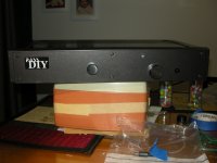
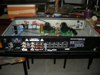
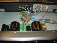
Thanks to Mr.Pass and this is my B1 I am still looking forward to find a case to finish it") it sounds perfectly good,it made me abandon my old tube preamp ha
it sounds perfectly good,it made me abandon my old tube preamp ha
!
I remove the input cap and use Holco 1K on the input resistor and AMTRANS carbon film 1K on the output resistor 。
About the output cap I am useing Mundorf 10uF parallel Rel-Cap 0.1uF paralle Jenson Copper Foil 0.01uF I can only say it is terrific!!
it sounds perfectly good,it made me abandon my old tube preamp ha!
I remove the input cap and use Holco 1K on the input resistor and AMTRANS carbon film 1K on the output resistor 。
About the output cap I am useing Mundorf 10uF parallel Rel-Cap 0.1uF paralle Jenson Copper Foil 0.01uF I can only say it is terrific!!
An externally hosted image should be here but it was not working when we last tested it.
B1 finished and working well
I just finished a B1 build using the PCB and JFETs from PassDIY and capacitors, Alps Pot and a 6 input rotary switch kit from HiFi Collective.
The case is my old NAD 1300 preamp (1990's vintage) which recently died - hence this project.
I also run the Oatley K303 RIAA amp in a separate box which is fine for my old turntable, a late 60's vintage Dual.
I'm powering the B1 off an old laptop computer PS. It seems to be OK.
I like this preamp. It works really well, sounds great. I need a new CD player now.
Attachments
You only need one DC blocking capacitor in each connection between your Source and Receiver.
If you already have DC blocking in your Receiver and you are happy with the size and quality of these capacitors then you can "not fit" the DC blocking capacitors on the output of the B1.
If you already have DC blocking in your Receiver and you are happy with the size and quality of these capacitors then you can "not fit" the DC blocking capacitors on the output of the B1.
Same for this fellow...
Hi Juanitox!
Have been wondering for a while about the same issue regarding my B1. So now I will remove the output cap on the B1(10 uF Asc polyprop). Or make a short instead of the caps - have some thin silver VanDenHul.
Will also change my Wima 1 uF on the input to a Obligato, since I use Obligato 10uF on my SIT. And the SIT is playing totally perfect!!
Have bought the New Sony SCD-XE800(sacd + SDS)player - and everything is nearly fully broken in now. And the sound?? - is
More and more fulfilling!!
Just waiting till end of summer - to build a version of ALP12P - to see if it gets more touch than my Alp10.2(Have room for 2 set with speakers).
B1 + SK82SIT is glorius.
Best
Olav
i'm going to build a B1 to go with my SIT amp who have an input capacitor. so can i leave the 10uf output cap and keep the 1K /220K output resistor ?
what about leaving the 1UF input cap
Hi Juanitox!
Have been wondering for a while about the same issue regarding my B1. So now I will remove the output cap on the B1(10 uF Asc polyprop). Or make a short instead of the caps - have some thin silver VanDenHul.
Will also change my Wima 1 uF on the input to a Obligato, since I use Obligato 10uF on my SIT. And the SIT is playing totally perfect!!
Have bought the New Sony SCD-XE800(sacd + SDS)player - and everything is nearly fully broken in now. And the sound?? - is
More and more fulfilling!!Just waiting till end of summer - to build a version of ALP12P - to see if it gets more touch than my Alp10.2(Have room for 2 set with speakers).
B1 + SK82SIT is glorius.
Best
Olav
You only need one capacitor between Source and B1 and another between B1 and Power Amp.
In the case of the DCB1 the components are carefully chosen to eliminate even those.
If your source is AC coupled you can delete the input cap. You might want to address the quality of the coupling.
If your Power Amp is AC coupled you can delete the output cap. You might want to address the quality of the coupling.
I personally chose to use MKP 1.0uFs at the input and 10uF PIO Obbligatos at the ouput and took out the coupling capacitors in my P.A.
- Status
- This old topic is closed. If you want to reopen this topic, contact a moderator using the "Report Post" button.
- Home
- Amplifiers
- Pass Labs
- B1 builders thread