Whatca know, you wait for ages for a bus and then 3 come together.
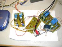
So here was last nights effort:
But then I realised that while I loved the small layout, it didn;t suit the large 1uF film caps I was going to use.
So then I went and did this one:
Much bigger board, and now I need a different case.
However, tonight I really struck gold and bought a PassDIY original!
So thanks Nelson and thanks Colin!
Fran
So here was last nights effort:
An externally hosted image should be here but it was not working when we last tested it.
An externally hosted image should be here but it was not working when we last tested it.
But then I realised that while I loved the small layout, it didn;t suit the large 1uF film caps I was going to use.
So then I went and did this one:
An externally hosted image should be here but it was not working when we last tested it.
An externally hosted image should be here but it was not working when we last tested it.
Much bigger board, and now I need a different case.
However, tonight I really struck gold and bought a PassDIY original!
So thanks Nelson and thanks Colin!
Fran
I don't know if this is of interest to anyone, but today I was playing around with ltspice and looking at what effect changing the pot value would have.
Well what I found was going up in resistance increases the amount of 2nd Harmonic distortion (ie going from a 25k pot to a 50k or 100k pot).
While I think a lot of people here are probably interested in minimising harmonic distortion some people might want to experimemnt with this to get more of a valve tone and hence increase the resistance of the pot.
I am planning on buying some cheap pots from Jaycar a 25k, 50k, and 100k and seeing if this effect is discernable to the ear.
The input impedance of the preamp will also increase by doing this.
I am not sure if their will be any negatives by doing this or not but it is definitely worth trying out if you want to inject some second harmonic to the sound of your system.
If anyone is interested I can post some screen grabs of the results.
Balanced Connections
I just thought I'd pass this along if anyone had the same question as me.
Q: Is there a modification for the B1 to use balanced/XLR connection on the input and output?
A: You can use two channels of a B1 to do balanced input to balanced output. Of course this also means dual pots for the level control. np
thanh1973 said:I don't know if this is of interest to anyone, but today I was playing around with ltspice and looking at what effect changing the pot value would have.
Well what I found was going up in resistance increases the amount of 2nd Harmonic distortion (ie going from a 25k pot to a 50k or 100k pot).
While I think a lot of people here are probably interested in minimising harmonic distortion some people might want to experimemnt with this to get more of a valve tone and hence increase the resistance of the pot.
I am planning on buying some cheap pots from Jaycar a 25k, 50k, and 100k and seeing if this effect is discernable to the ear.
The input impedance of the preamp will also increase by doing this.
I am not sure if their will be any negatives by doing this or not but it is definitely worth trying out if you want to inject some second harmonic to the sound of your system.
If anyone is interested I can post some screen grabs of the results.
I'm interested. This was discussed early, and I'd like to see at least 1khz and 10 khz, and .1 and 1V 10 V
The paper I saw said it should be worse as level and frequency go up. I'm still sorting out how to reliably measure the distortion. It's so low you really need to have a good scheme to get down there, and know you actually measured something versus finding the measurement equipment noise floor. .
Re: Balanced Connections
Or, you could do this
http://sound.westhost.com/project51.htm
Put the Balance Line receiver before the B1, or right on its inputs in a little p2p or veroboard. You can then leave everthing as it is after that addition and have the B1 give SE output to your amp if your amp has RCAs as an input or you can put the Balanced Line Transmitter on the output of your B1 if your amp has balanced inputs.
Uriah
The advantage is cost probably much more than performance as putting the signal through a few opamps might not be to your liking as much at two B1s but then again would the B1s need have 2sk170 matched on both boards for a total of 4 matched 2sk170? Dont know. And do you want to get fiddly with more pots? Give and take on both options.
Uriah
zcables said:I just thought I'd pass this along if anyone had the same question as me.
Q: Is there a modification for the B1 to use balanced/XLR connection on the input and output?
A: You can use two channels of a B1 to do balanced input to balanced output. Of course this also means dual pots for the level control. np
Or, you could do this
http://sound.westhost.com/project51.htm
Put the Balance Line receiver before the B1, or right on its inputs in a little p2p or veroboard. You can then leave everthing as it is after that addition and have the B1 give SE output to your amp if your amp has RCAs as an input or you can put the Balanced Line Transmitter on the output of your B1 if your amp has balanced inputs.
Uriah
The advantage is cost probably much more than performance as putting the signal through a few opamps might not be to your liking as much at two B1s but then again would the B1s need have 2sk170 matched on both boards for a total of 4 matched 2sk170? Dont know. And do you want to get fiddly with more pots? Give and take on both options.
Uriah
Re: Re: Balanced Connections
Uriah - I believe you responded to me earlier in this thread after which I found the project above. I also found what looks like an extremely high-quality chip (THAT 1200 family) which would be ideal - so I will try to get hold of the various versions of this chip (0db, -3db and -6 db) and implement a simple receiver.
I like the idea of using two B1's and putting the receiver at the input of the various FW amps I am attempting to build.
Alan
udailey said:
Or, you could do this
http://sound.westhost.com/project51.htm
Put the Balance Line receiver before the B1, or right on its inputs in a little p2p or veroboard. You can then leave everthing as it is after that addition and have the B1 give SE output to your amp if your amp has RCAs as an input or you can put the Balanced Line Transmitter on the output of your B1 if your amp has balanced inputs.
Uriah
The advantage is cost probably much more than performance as putting the signal through a few opamps might not be to your liking as much at two B1s but then again would the B1s need have 2sk170 matched on both boards for a total of 4 matched 2sk170? Dont know. And do you want to get fiddly with more pots? Give and take on both options.
Uriah
Uriah - I believe you responded to me earlier in this thread after which I found the project above. I also found what looks like an extremely high-quality chip (THAT 1200 family) which would be ideal - so I will try to get hold of the various versions of this chip (0db, -3db and -6 db) and implement a simple receiver.
I like the idea of using two B1's and putting the receiver at the input of the various FW amps I am attempting to build.
Alan
I think you would get the same result, minus a B1 if you do the receiver at the front of the B1 and not the transmitter at the end of it. Dont you? You still end up with RCA inputs on the amps and you still get to convert the balanced signal to SE but you only need 1 B1.
Uriah
Uriah
udailey said:I think you would get the same result, minus a B1 if you do the receiver at the front of the B1 and not the transmitter at the end of it. Dont you? You still end up with RCA inputs on the amps and you still get to convert the balanced signal to SE but you only need 1 B1.
Uriah
Uriah - I will do the simple approach first as you suggest, then try running!
Alan
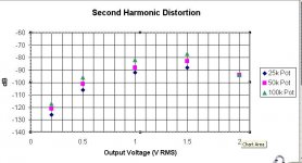
Well here are some ltspice measurements (2nd Harmonic) done with different pots at various output voltages.
The results were not what I expected (ie the trend of results)
Also one other point, the difference in distortion between pots may not be great enough to discern the difference by ear. So those hoping to inject some tube/valve tone may not notice the difference.
I did do some measurements with a 1Meg pot which gave more significant distortion but I would be a little worried putting in a 1Meg pot that it might have some other negative effect.
The measurements were done at 1000Hz using a 47k resitive load.
It would be interesting how these might correlate with real measurements.
Attachments
it is fairly common knowledge that most amplifiers perform better when Rs is kept low.
In particular distortion rises as Rs rises.
Your results simply confirm this.
That's why you need to be very careful when using passive pots to drive anything.
try 10k pot and 1k0 pot and add those results to your graph.
The 1k0 pot is equivalent to Rs<=250r.
In particular distortion rises as Rs rises.
Your results simply confirm this.
That's why you need to be very careful when using passive pots to drive anything.
try 10k pot and 1k0 pot and add those results to your graph.
The 1k0 pot is equivalent to Rs<=250r.
What I found unusual (to me that is) was that max distortion occured with pot at 3 O'Clock
I am not keen on the idea of dropping the value of the pot to below 10k as this will present a very difficult load to the cd player, and since the B1 has a relatively low output impedance regardless of the pot used, my feeling is a higher value pot would be a better choice (espescially for the cd player.)
I am not keen on the idea of dropping the value of the pot to below 10k as this will present a very difficult load to the cd player, and since the B1 has a relatively low output impedance regardless of the pot used, my feeling is a higher value pot would be a better choice (espescially for the cd player.)
I'm not suggesting that you adopt a very low value of pot.
All I'm asking is that you complete the investigation to see if your results can confirm an optimum Rs that allows the buffer (amplifier) to work at it's best.
Measure the resistance on both sides of the wiper when set to 3 o'clock. Is this the -6dB position? If so then it also presents the highest output impedance and again confirms that high Rs is a direct contributor to non optimal distortion.
If you find that the B1 likes to see a pot value between 10k and 20k at it's input, then you have provided good information for other users.
thanh1973 said:Just to be sure there is no misunderstanding.
These measurements were taken of the B1 buffer using different pots.
The input voltage was held constant at 2V RMS and the output voltage was adjusted by adjusting the value of the pot.
Thanks for posting. Are you using the actual Toshiba 2SK170 JFET parameters, or "generic" JFET to generate these?
From above, the -6 dB position would be the 1V middle readings, which would be the highest source impedance. Oddly they are not highest distortion.
Also very interesting is a 10dB difference between 25K pot and 100K pot. This is a factor of 3X, and is certainly measureable. I can measure to verify the highest distortion spot, 1.5V, my gear can do that easily.
I'd love to see the same runs at 10kHz if possible.
Needing my share of fun, I just popped this together. J-FET BoZ, followed by a B1 buffer Works out in the most splendid fashion. Will drive a F5 really well, and most every other poweramp. (With the sore excuse, being the F4 )
BTW its Tony's B1 board, I made the others
Works out in the most splendid fashion. Will drive a F5 really well, and most every other poweramp. (With the sore excuse, being the F4 )BTW its Tony's B1 board, I made the others
Attachments
I am using LSK170 parameters from linear systems.
I also did some using Toshiba 2sk170 parameters (not shown here) which gave lower distortion numbers than the Linear Systems model.
I will confirm later whether the Toshiba model exhibits the same behaviour as Linear systems.
I also did some using Toshiba 2sk170 parameters (not shown here) which gave lower distortion numbers than the Linear Systems model.
I will confirm later whether the Toshiba model exhibits the same behaviour as Linear systems.
steenoe said:Only Toshiba is good, everything else has noise figures going through the roof!!! '(In comparison) He-he, i might add.... Toshiba rules
Just a personal oppinion.
seems that your Pumpie is made with 2SK369 ?

- Home
- Amplifiers
- Pass Labs
- B1 Buffer Preamp